
Imagine a factory where many electric motors, welding machines, and compressors operate all day. At the end of the month, the electricity bill arrives and it is much higher than expected. After inspection, engineers discover that the problem is not only high energy consumption but also a low power factor.
A low power factor means electrical power is not being used efficiently. Utilities often charge penalties to industries that operate with poor power factor. This is where a Power Factor Correction Project becomes very important.
Power factor correction improves electrical efficiency by reducing reactive power in the system. It helps industries reduce electricity bills, improve system stability, and increase the capacity of electrical equipment.
For electrical students and beginners, building a power factor correction project is an excellent way to understand power systems, capacitors, reactive power, and energy efficiency.
In this guide, you will learn:
- What a Power Factor Correction Project is
- Power factor correction project working principle
- Types of power factor correction systems
- Important components used in the project
- Power factor correction project advantages and disadvantages
- Real-world power factor correction project applications
This article explains the topic in simple language so electrical students, technicians, and engineers can easily understand and apply the concept in practical systems.
What is Power Factor Correction Project?
A Power Factor Correction Project is an electrical system or experimental project designed to improve the power factor of an electrical circuit by reducing reactive power using capacitors or electronic controllers.
Simple Definition
Power factor correction is the process of improving the efficiency of an electrical system by minimizing the phase difference between voltage and current.
Simple Explanation
In many electrical systems, especially those using motors or inductive loads, the current does not flow exactly in phase with the voltage. This phase difference reduces efficiency and causes power losses.
Power factor correction solves this problem by adding capacitors or other compensation devices that bring voltage and current closer in phase.
Practical Example
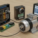
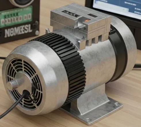
Consider a factory that operates several induction motors. These motors consume reactive power, which lowers the power factor.
By installing capacitor banks or automatic power factor correction panels, the system compensates for reactive power and improves overall electrical efficiency.
A Power Factor Correction Project demonstrates this concept practically using measurement circuits and capacitor banks.
Power Factor Correction Project Working Principle
The power factor correction project working principle is based on compensating reactive power in electrical circuits.
In an inductive system, current lags behind voltage. This lagging current creates reactive power, which reduces the power factor.
Capacitors are used to supply leading reactive power that cancels the lagging reactive power.
Think of it like balancing two opposite forces.
Step-by-Step Working Process
The project typically works through the following steps.
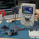
1. Measuring Voltage and Current
Sensors measure:
- Supply voltage
- Current flowing through the load
These measurements help determine the system power factor.
2. Calculating Power Factor
The controller or measuring circuit calculates the power factor using the relationship between voltage and current.
Power factor values range between:
- 0 (very poor efficiency)
- 1 (perfect efficiency)
3. Detecting Low Power Factor
If the system detects that the power factor is below a desired level, corrective action is required.
4. Switching Capacitor Banks
Capacitors are automatically or manually connected to the circuit.
Capacitors supply reactive power that offsets inductive reactive power.
5. Power Factor Improvement
After capacitor compensation:
- Current and voltage become more aligned
- Power factor improves
- System efficiency increases
This simple but powerful concept forms the basis of power factor correction systems used in industries worldwide.
Types / Classification of Power Factor Correction Systems
Power factor correction systems can be classified based on their method of operation.
Manual Power Factor Correction
In this system, capacitors are manually connected to the electrical system.
Technicians switch capacitor banks depending on the load conditions.
Although simple, it requires constant monitoring.
Automatic Power Factor Correction (APFC)
Automatic power factor correction systems use controllers to monitor the power factor continuously.
When power factor drops below the required level, capacitor banks automatically switch on.
This system is widely used in industrial installations.
Static Power Factor Correction
Static correction uses fixed capacitors connected directly to the load.
It is commonly used for:
- Small motors
- Lighting systems
- Small industrial loads
Dynamic Power Factor Correction
Dynamic correction systems use advanced electronic devices such as power electronics controllers.
These systems respond quickly to changing load conditions and provide fast power factor correction.
Main Components of Power Factor Correction Project
Several electrical and electronic components are used in a power factor correction project.
Capacitor Bank
Capacitors are the most important component.
Their function is to provide leading reactive power that compensates for inductive loads.
Capacitor banks are widely used in industries for power factor correction.
Power Factor Controller
The controller measures the power factor and controls the switching of capacitor banks.
It ensures the system maintains the desired power factor level.
Current Transformer (CT)
Current transformers measure the current flowing through the load.
This information is used to calculate power factor.
Voltage Sensor
Voltage sensors measure the supply voltage.
Accurate voltage measurement is necessary for correct power calculations.
Switching Devices
Switching devices connect or disconnect capacitor banks from the system.
Examples include:
- Contactors
- Relays
- Solid-state switches
Display Unit
A display unit shows important parameters such as:
- Voltage
- Current
- Power factor
This helps users monitor system performance.
Power Factor Correction Project Advantages and Disadvantages
Understanding power factor correction project advantages and disadvantages helps engineers evaluate its importance.
Advantages
- Improves electrical system efficiency
- Reduces electricity bills for industries
- Decreases power losses in transmission lines
- Increases capacity of electrical equipment
- Improves voltage stability
- Reduces utility penalty charges
- Enhances overall power quality
These benefits make power factor correction essential in modern electrical systems.
Disadvantages / Limitations
Although useful, power factor correction systems have some limitations.
- Initial installation cost may be high
- Capacitor banks require maintenance
- Incorrect capacitor sizing can cause overcorrection
- Harmonic distortion may occur in some systems
Proper design and installation can minimize these issues.
Power Factor Correction Project Applications
Power factor correction project applications are widely found in modern electrical systems.
Industrial Applications
Industries are the largest users of power factor correction systems.
Examples include:
- Manufacturing plants
- Steel industries
- Cement factories
- Textile mills
These facilities operate many inductive loads that require power factor improvement.
Commercial Applications
Commercial buildings also benefit from power factor correction.
Applications include:
- Shopping malls
- Office buildings
- Hotels
- Hospitals
Improving power factor reduces electricity costs.
Power Distribution Systems
Utility companies use power factor correction to improve transmission efficiency and reduce losses.
Renewable Energy Systems
Power factor correction helps maintain stable operation in systems with solar inverters and renewable power sources.
Comparison: Manual vs Automatic Power Factor Correction
Understanding the difference between manual power factor correction and automatic power factor correction helps engineers select the appropriate system.
| Feature | Manual Power Factor Correction | Automatic Power Factor Correction |
| Operation | Manual switching | Automatic control |
| Monitoring | Requires operator | Continuous monitoring |
| Efficiency | Moderate | High |
| Cost | Lower | Higher |
| Reliability | Depends on operator | Highly reliable |
Automatic systems are preferred in large industrial installations.
Selection Guide
Choosing the right power factor correction system requires careful planning.
Determine Load Type
Identify whether the system contains inductive loads such as motors, transformers, or welding machines.
Calculate Required Capacitor Rating
Capacitor banks should be selected based on required reactive power compensation.
Choose Automatic Controllers
Industries should use automatic power factor correction systems for better control.
Consider Harmonic Protection
If the system contains nonlinear loads, harmonic filters may be required.
Common Problems & Solutions
Students working on power factor correction projects may face several practical issues.
Why is the power factor not improving?
Possible causes:
- Incorrect capacitor size
- Faulty capacitor bank
- Incorrect wiring
Solution:
- Recalculate capacitor rating
- Replace damaged capacitors
- Check circuit connections
Why are capacitors overheating?
Possible causes:
- Overvoltage conditions
- Harmonic currents
- Poor ventilation
Solution:
- Check voltage levels
- Install harmonic filters
- Improve cooling
Why does the controller not switch capacitors?
Possible causes:
- Controller configuration error
- Faulty relay or contactor
- Sensor failure
Solution:
- Check controller settings
- Inspect switching devices
- Replace sensors
Future Trends in Power Factor Correction Technology
Power factor correction technology continues to evolve.
Smart Power Factor Controllers
Modern controllers use digital technology to improve accuracy and monitoring capabilities.
IoT-Based Energy Monitoring
IoT systems allow remote monitoring of power factor and energy consumption.
Active Power Factor Correction
Active correction systems use power electronics to improve power factor more efficiently.
Smart Grid Integration
Future power systems will integrate power factor correction with smart grid technologies to improve energy management.
Conclusion
The Power Factor Correction Project is an important concept in electrical engineering that improves the efficiency of power systems. Low power factor is a common problem in electrical systems that use inductive loads such as motors and transformers.
Understanding the power factor correction project working principle helps electrical students learn how capacitors compensate for reactive power and improve system performance. Using capacitor banks, controllers, and monitoring circuits, power factor correction systems help reduce energy losses and improve electrical efficiency.
The power factor correction project advantages and disadvantages show that although installation may require investment, the long-term benefits include reduced electricity bills, improved voltage stability, and increased equipment capacity.
Power factor correction project applications are widely used in industries, commercial buildings, and power distribution systems. As modern energy systems evolve, power factor correction technology will continue to play an important role in improving energy efficiency and sustainable power management.