Imagine you are repairing an electronic circuit, but the device is not working properly. You check the voltage using a multimeter, and it shows the correct value. However, the circuit still fails. The problem might not be the voltage level—it could be the shape of the signal. This is where an oscilloscope becomes an essential tool.
An oscilloscope allows engineers and technicians to see electrical signals in real time. Instead of just showing a number like a multimeter, it displays a waveform that reveals how voltage changes over time. This ability makes it possible to diagnose problems in power supplies, communication systems, microcontrollers, and many other electronic circuits.
For electrical students and beginners, understanding Oscilloscope Basics is very important because oscilloscopes are widely used in laboratories, repair workshops, and industrial environments.
In this guide, you will learn the oscilloscope working principle, types, main components, practical oscilloscope applications, and the oscilloscope advantages and disadvantages. The explanations are simple and practical so beginners can clearly understand how this powerful diagnostic instrument works.
2. What is an Oscilloscope?
An oscilloscope is an electronic measuring instrument used to display and analyze electrical signals in the form of waveforms.
Simple Definition
An oscilloscope is a device that shows how voltage changes over time by displaying signals on a screen as graphical waveforms.
Simple Explanation
Unlike a multimeter that gives only a numerical value, an oscilloscope provides a visual representation of the signal. This helps engineers understand:
- Signal shape
- Signal frequency
- Signal amplitude
- Signal noise or distortion
Practical Example
Consider a microcontroller output signal.
Using a multimeter, you may read 5 volts. However, the oscilloscope might reveal that the signal is actually a square wave switching between 0V and 5V.
This visual information helps engineers analyze circuit behavior more accurately.
3. Oscilloscope Working Principle
The oscilloscope working principle is based on measuring voltage and displaying it graphically against time.
An oscilloscope converts electrical signals into visual waveforms on a display screen.
Step-by-Step Working Process
Signal Input
The electrical signal enters the oscilloscope through a probe.
Signal Attenuation or Amplification
The input signal is adjusted using vertical control circuits to fit the display range.
Vertical Deflection
The voltage level controls the vertical movement of the waveform on the screen.
Time Base Generator
A timing circuit creates a horizontal sweep that moves the waveform across the screen.
Horizontal Deflection
The signal moves from left to right based on time.
Display System
The waveform appears on the screen showing voltage vs time.
Simple Analogy
Think of an oscilloscope like a heart monitor in a hospital.
Just as a heart monitor displays heartbeats as waves, an oscilloscope displays electrical signals as waveforms.
4. Types of Oscilloscopes
Oscilloscopes are classified based on their technology and functionality.
Analog Oscilloscope
Analog oscilloscopes use cathode ray tube (CRT) technology to display signals.
Features
- Continuous waveform display
- Simple operation
- Limited storage capability
Applications
- Educational laboratories
- Basic signal analysis
Digital Storage Oscilloscope (DSO)
A digital storage oscilloscope converts signals into digital data and stores them in memory.
Features
- Signal storage
- High accuracy
- Advanced measurement functions
Applications
- Electronics testing
- Communication systems
- Industrial diagnostics
Digital Phosphor Oscilloscope (DPO)
DPO oscilloscopes provide high-speed waveform capture and display complex signals.
Features
- Real-time waveform analysis
- Better visualization of signal variations
Applications
- High-speed electronics
- Embedded system development
USB Oscilloscope
USB oscilloscopes connect directly to a computer.
Features
- Portable design
- Software-based interface
- Lower cost
Applications
- Field testing
- Educational purposes
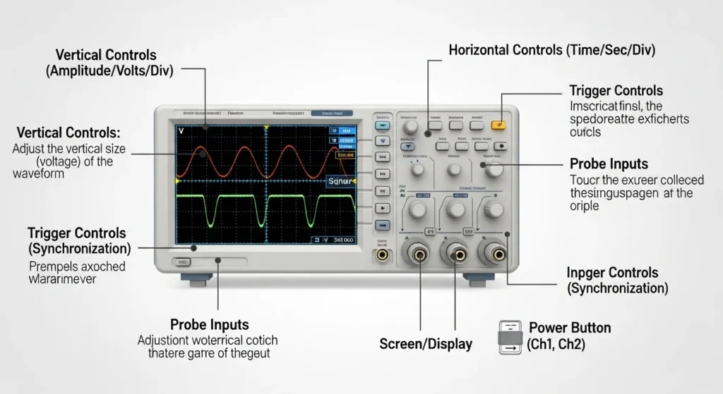
5. Main Components of an Oscilloscope
An oscilloscope consists of several important components that work together to display signals.
Display Screen
The display screen shows the waveform of the electrical signal.
In modern oscilloscopes, this is usually an LCD screen.
Input Probe
The probe connects the oscilloscope to the circuit under test.
Functions:
- Transfers signal to the oscilloscope
- Reduces signal distortion
Vertical System
This system controls the amplitude (voltage level) of the waveform.
Functions:
- Amplifies or attenuates signals
- Adjusts vertical scaling
Horizontal System
This system controls the time axis.
Functions:
- Generates sweep signals
- Controls time per division
Trigger Circuit
The trigger circuit stabilizes the waveform display.
Without triggering, the waveform would appear unstable.
Power Supply
The power supply provides energy for all internal circuits.
6. Oscilloscope Advantages
Oscilloscopes provide many benefits in electronics testing and troubleshooting.
Oscilloscope Advantages and Disadvantages
Advantages
- Displays real-time signal waveforms
- Measures frequency, voltage, and time intervals
- Detects signal noise and distortion
- Helps troubleshoot complex circuits
- Essential for communication and digital electronics
- Allows waveform storage and analysis
These advantages make oscilloscopes one of the most important instruments in electrical engineering.
7. Oscilloscope Disadvantages
Despite their usefulness, oscilloscopes also have some limitations.
Disadvantages
- More expensive than basic measuring instruments
- Requires training to use properly
- Large and bulky in some models
- Sensitive to electrical noise
- Limited voltage measurement range without probes
Understanding these limitations helps engineers use oscilloscopes more effectively.
8. Oscilloscope Applications
Oscilloscopes are widely used in electrical, electronic, and communication systems.
Electronics Testing
Engineers use oscilloscopes to analyze signals in electronic circuits.
Examples:
- Amplifiers
- Power supplies
- Microcontrollers
Communication Systems
Oscilloscopes help analyze signals in communication networks.
Examples:
- RF signals
- Digital communication signals
- Signal modulation
Industrial Maintenance
Technicians use oscilloscopes to diagnose faults in industrial equipment.
Examples:
- Motor drives
- Control circuits
- Automation systems
Automotive Electronics
Modern vehicles contain complex electronic systems.
Oscilloscopes help test:
- Sensors
- Ignition systems
- ECU signals
Educational Laboratories
Students use oscilloscopes to understand signal behavior and circuit operation.
These examples demonstrate the wide range of oscilloscope applications in modern technology.
9. Comparison: Oscilloscope vs Multimeter
Students often ask about the difference between oscilloscope and multimeter.
| Feature | Oscilloscope | Multimeter |
| Measurement Type | Visual waveform display | Numerical values |
| Signal Analysis | Detailed signal analysis | Basic measurement |
| Parameters | Voltage, frequency, time | Voltage, current, resistance |
| Complexity | Advanced instrument | Simple instrument |
| Applications | Circuit analysis | Basic electrical testing |
Both tools are important, but oscilloscopes provide deeper signal analysis.
10. Selection Guide
Choosing the right oscilloscope depends on several important factors.
Bandwidth
Bandwidth determines the maximum signal frequency the oscilloscope can measure.
Higher bandwidth allows accurate measurement of fast signals.
Sampling Rate
Sampling rate determines how many signal samples are captured per second.
Higher sampling rates improve waveform accuracy.
Number of Channels
Oscilloscopes may have:
- 2 channels
- 4 channels
More channels allow simultaneous measurement of multiple signals.
Memory Depth
Memory depth determines how long signals can be stored.
Tip for Beginners
A digital storage oscilloscope (DSO) with moderate bandwidth is a good starting option.
11. Common Problems & Solutions
Unstable Waveform
Cause:
Improper triggering.
Solution:
Adjust trigger level and mode.
Incorrect Voltage Reading
Cause:
Wrong probe setting.
Solution:
Check probe attenuation (1x or 10x).
No Signal Display
Cause:
Improper connection or wrong input channel.
Solution:
Verify probe connection and channel selection.
Noisy Signal
Cause:
External electrical interference.
Solution:
Use proper grounding and shielding.
12. Future Trends in Oscilloscope Technology
Oscilloscope technology continues to improve with new innovations.
High-Speed Digital Oscilloscopes
Modern oscilloscopes can analyze gigahertz-level signals used in advanced communication systems.
AI-Assisted Signal Analysis
Future oscilloscopes may use artificial intelligence to automatically detect signal faults.
Portable Oscilloscopes
Compact and handheld oscilloscopes are becoming more common for field technicians.
Cloud-Based Data Storage
Engineers will be able to store and analyze waveforms remotely.
Integration with Embedded Systems
Oscilloscopes will integrate directly with development environments used for embedded system design.
These advancements will further expand oscilloscope applications in modern electronics.
13. Conclusion
Understanding Oscilloscope Basics is essential for electrical students, engineers, and technicians who work with electronic circuits and signal analysis. Unlike basic measuring instruments, an oscilloscope allows users to visualize electrical signals in real time, making it easier to analyze waveform characteristics such as amplitude, frequency, and timing.
In this article, we explored the oscilloscope working principle, major components, types, and practical oscilloscope applications across electronics, industry, automotive systems, and educational laboratories. We also discussed the oscilloscope advantages and disadvantages, helping beginners understand when and how to use this instrument effectively.
As modern electronics continue to become more complex, oscilloscopes will remain one of the most valuable tools for diagnosing circuit problems and analyzing signal behavior. For anyone entering the field of electrical or electronics engineering, mastering oscilloscope fundamentals is an important step toward becoming a skilled technician or engineer.