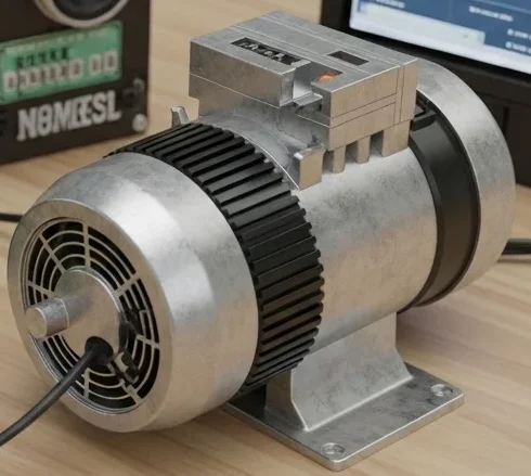

Imagine connecting a fan to an electrical supply and noticing that the wires become warm after some time. Now imagine connecting a coil or capacitor in an AC circuit and observing that the current behavior changes without producing much heat. These two situations involve two very important electrical concepts: resistance and reactance.
In electrical and electronic systems, understanding the difference between resistance and reactance is essential because both affect how current flows in a circuit. Resistance opposes current flow by converting electrical energy into heat, while reactance opposes alternating current due to magnetic or electric fields. Together, they play a major role in AC circuit behavior, power systems, motors, transformers, filters, and electronic devices.
For students, engineers, technicians, and beginners, learning these concepts builds a strong foundation in circuit analysis and electrical design. Without understanding resistance and reactance, it becomes difficult to analyze voltage drops, power losses, and AC system performance.
In this article, you will learn resistance and reactance definitions, working principles, types, advantages and disadvantages, applications, practical comparisons, troubleshooting methods, and future trends. The explanations are simple, practical, and designed to help you understand these concepts clearly.
What is Resistance and Reactance?
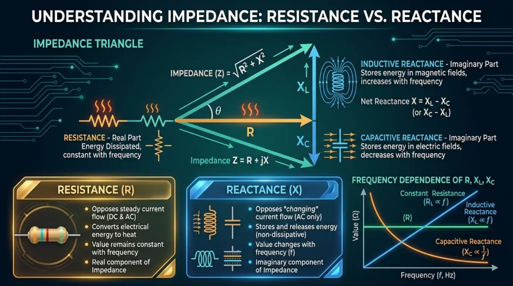
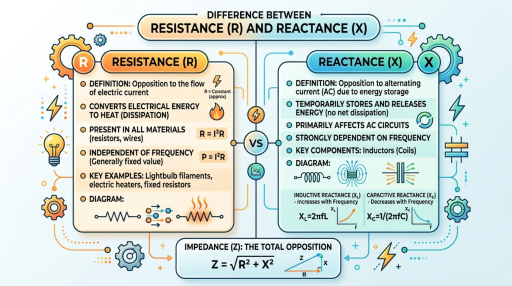
Resistance and reactance are two important properties that oppose the flow of electric current in a circuit, but they work in different ways. Resistance is the opposition to the flow of current in both AC (Alternating Current) and DC (Direct Current) circuits. It converts electrical energy into heat and remains constant regardless of the supply frequency. It is measured in ohms (Ω). Reactance, on the other hand, opposes the flow of current only in AC circuits. It is caused by inductors and capacitors, which store and release energy in magnetic and electric fields instead of converting it into heat. Unlike resistance, reactance changes with the frequency of the AC supply. Together, resistance and reactance combine to form impedance, which represents the total opposition to current flow in an AC circuit. Understanding these concepts is essential for designing, analyzing, and troubleshooting electrical and electronic systems.
What is Resistance?
Resistance is the property of a material or component that opposes the flow of electric current. It converts electrical energy into heat.
Resistance exists in both AC and DC circuits.
Simple Explanation
Resistance acts like friction in a water pipe. If the pipe is narrow, water flow becomes difficult. Similarly, resistance makes current flow harder.
Practical Example
An electric heater uses resistance to produce heat.
Resistance Formula
The basic resistance formula is:
genui{“math_block_widget_always_prefetch_v2”:{“content”:”R=\frac{V}{I}”}}
Where:
- ( R ) = Resistance
- ( V ) = Voltage
- ( I ) = Current
Resistance is measured in Ohms (Ω).
What is Reactance?
Reactance is the opposition offered to alternating current (AC) due to inductors and capacitors.
Unlike resistance, reactance does not usually waste energy as heat.
Simple Explanation
Reactance behaves like a spring resisting rapid movement changes.
It only appears significantly in AC circuits because AC changes direction continuously.
Practical Example
A ceiling fan motor contains inductive reactance that controls current flow.
Reactance Formula
Inductive reactance is given by:
X_L=2\pi fL
Capacitive reactance is:
X_C=\frac{1}{2\pi fC}
Where:
( X_L ) = Inductive reactance
( X_C ) = Capacitive reactance
( f ) = Frequency
( L ) = Inductance
( C ) = Capacitance
Resistance and Reactance Working Principle
Resistance Working Principle
The working principle of resistance is based on the opposition it provides to the flow of electric current through a conductor. When electrical current passes through a resistive material, such as carbon, nichrome, or metal alloys, the moving electrons collide with the atoms of the material. These collisions slow down the flow of electrons and convert a portion of the electrical energy into heat. The amount of resistance depends on the material, length, cross-sectional area, and temperature of the conductor. Unlike reactance, resistance works in both AC (Alternating Current) and DC (Direct Current) circuits and does not depend on the supply frequency. This property allows resistors to control current, divide voltage, limit power, and protect electrical and electronic circuits from excessive current.
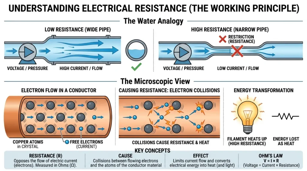
The resistance working principle is based on electron collision inside a conductor.
Step-by-Step Process
Voltage is applied to a conductor
Electrons start moving
Electrons collide with atoms
Energy converts into heat
Current flow becomes limited
Easy Analogy
Imagine people walking through a crowded hallway.
More crowd means harder movement.
Resistance works similarly by restricting electron flow.
Important Features of Resistance
Works in AC and DC circuits
Produces heat
Independent of frequency
Measured in Ohms
Reactance Working Principle
The working principle of reactance is based on the ability of inductors and capacitors to oppose the flow of alternating current (AC) by storing and releasing energy. Unlike resistance, reactance does not consume electrical energy as heat. Instead, it temporarily stores energy in a magnetic field (inductive reactance) or an electric field (capacitive reactance) and then returns it to the circuit. In an inductor, the changing current creates a magnetic field that opposes changes in current flow, while in a capacitor, the changing voltage creates an electric field that opposes changes in voltage. The amount of reactance depends on the frequency of the AC supply. As the frequency increases, inductive reactance increases, whereas capacitive reactance decreases. This property makes reactance an essential factor in AC circuit analysis, power systems, filters, and electrical equipment design.
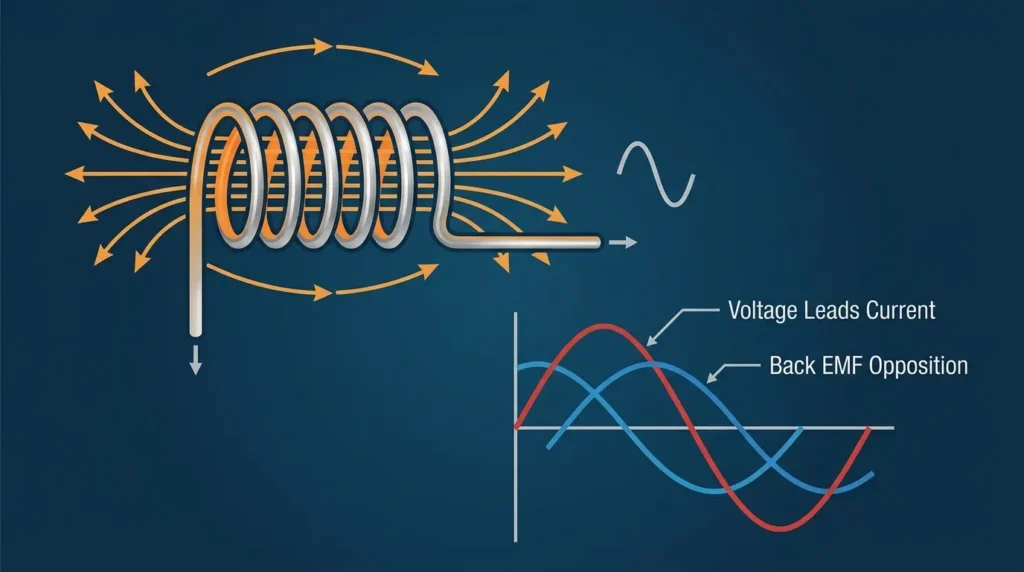
The reactance working principle depends on magnetic and electric field effects in AC circuits.
Step-by-Step Process
AC voltage changes continuously
Inductors create magnetic fields
Capacitors store electric charge
These effects oppose current changes
Current becomes delayed or advanced
Easy Analogy
Imagine pushing a swing.
The swing does not respond instantly because energy is stored and released continuously.
Reactance behaves similarly in AC circuits.
Important Features of Reactance
Exists only in AC circuits
Depends on frequency
Stores energy temporarily
Does not mainly produce heat
Types / Classification
Types of Resistance
Fixed Resistance
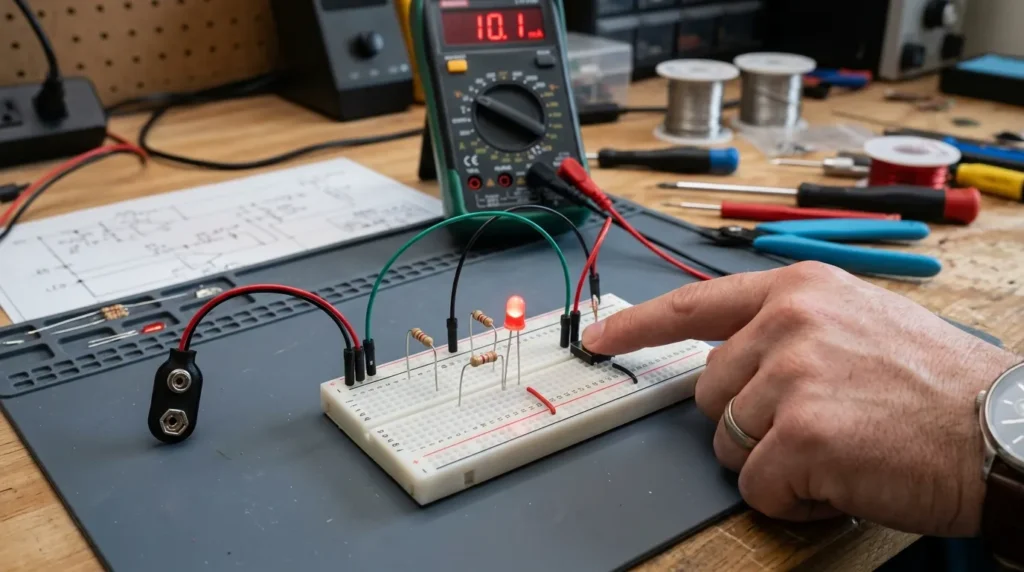
A fixed resistance is a type of resistor that has a constant resistance value and cannot be adjusted after it is manufactured. It is designed to provide a specific amount of opposition to the flow of electric current in an electrical circuit. Fixed resistors are made from materials such as carbon, metal film, wire wound, or metal oxide, depending on the application. They are widely used in electronic circuits to limit current, divide voltage, protect components, and control signal levels. Because their resistance value remains stable during normal operation, fixed resistors are reliable and commonly found in household appliances, power supplies, communication equipment, industrial control systems, and electronic devices. They are available in a wide range of resistance values, power ratings, and tolerance levels to meet different circuit requirements.
Fixed resistors have constant resistance values.
Applications
Electronic circuits
LED circuits
Voltage dividers
Variable Resistance
Variable resistors allow resistance adjustment.
Examples
Potentiometers
Rheostats
Applications
Volume controls
Speed regulators
Temperature-Dependent Resistance
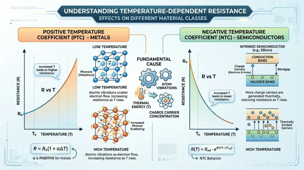
Temperature-dependent resistance refers to a resistor whose resistance value changes automatically with temperature. These resistors, commonly known as thermistors, are designed to either increase or decrease their resistance as the surrounding temperature changes. There are two main types: Negative Temperature Coefficient (NTC) thermistors, whose resistance decreases as temperature increases, and Positive Temperature Coefficient (PTC) thermistors, whose resistance increases with rising temperature. Temperature-dependent resistors are widely used for temperature sensing, overheating protection, battery management systems, motor protection, and electronic control circuits. Their ability to respond quickly to temperature changes makes them essential components in modern electrical and electronic applications.
Resistance changes with temperature.
Examples
- Thermistors
Applications
Temperature sensors
Protection circuits
Types of Reactance
Inductive Reactance
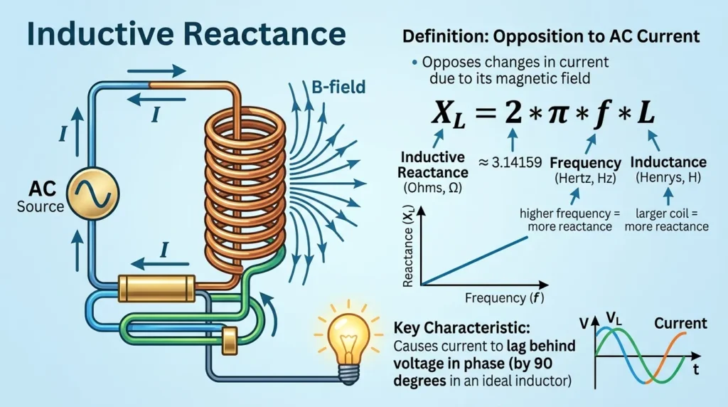
Inductive reactance is the opposition that an inductor offers to the flow of alternating current (AC). It is produced when the changing AC current creates a changing magnetic field around the inductor, which induces a voltage that opposes the change in current according to Lenz’s Law. Unlike resistance, inductive reactance does not consume electrical energy; instead, it temporarily stores energy in the magnetic field and returns it to the circuit. The value of inductive reactance depends on both the inductance (L) of the coil and the frequency (f) of the AC supply. As the frequency increases, the inductive reactance also increases, making it more difficult for AC current to flow. Inductive reactance is measured in ohms (Ω) and plays an important role in transformers, motors, generators, power systems, filters, and AC circuit design.
Inductive reactance occurs in inductors.
Features
Increases with frequency
Current lags voltage
Applications
Motors
Transformers
Chokes
Capacitive Reactance
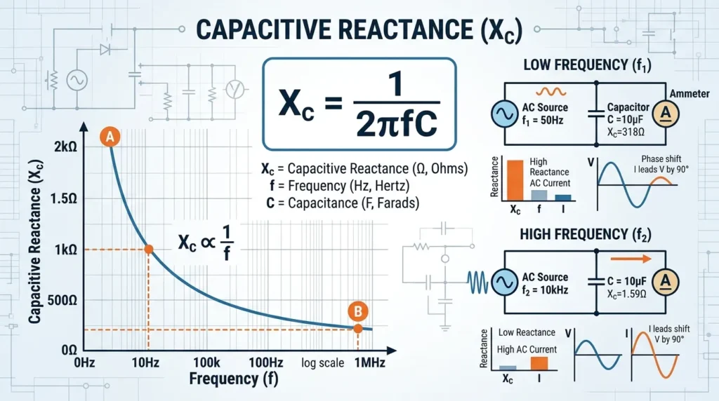
Capacitive reactance is the opposition that a capacitor offers to the flow of alternating current (AC). It occurs because a capacitor continuously charges and discharges as the AC voltage changes, creating an electric field that opposes changes in voltage. Unlike resistance, capacitive reactance does not convert electrical energy into heat. Instead, it temporarily stores energy in the electric field and then releases it back into the circuit. The value of capacitive reactance depends on the capacitance (C) of the capacitor and the frequency (f) of the AC supply. As the frequency increases, the capacitive reactance decreases, allowing more AC current to flow through the circuit. Capacitive reactance is measured in ohms (Ω) and is widely used in power factor correction, AC filters, coupling and decoupling circuits, communication systems, and electronic equipment.
Capacitive reactance occurs in capacitors.
Features
Decreases with frequency
Current leads voltage
Applications
Filters
Power factor correction
Coupling circuits
Main Components
Components Related to Resistance
Resistors
Resistors provide controlled opposition to current.
Conductors
Wire materials affect resistance value.
Heating Elements
Used where resistance heating is required.
Components Related to Reactance
Inductors
Store energy in magnetic fields.
Capacitors
Store energy in electric fields.
AC Sources
Reactance depends on alternating current frequency.
Advantages
Advantages of Resistance
Simple circuit control
Useful for heating applications
Easy voltage division
Stable operation
Low manufacturing cost
Real-World Benefits
Resistance helps control current safely in household and industrial systems.
Advantages of Reactance
Efficient energy storage
Improves power factor
Reduces power loss in some systems
Important for filtering signals
Supports AC motor operation
Real-World Benefits
Reactance allows transformers, motors, and communication systems to operate efficiently.
Disadvantages / Limitations
Disadvantages of Resistance
Produces heat losses
Reduces efficiency
Causes voltage drop
Energy wastage in high-current systems
Disadvantages of Reactance
Complicates AC circuit analysis
Causes phase shift
Can reduce power factor
Difficult for beginners to understand
Resistance and Reactance Applications
Resistance Applications
Home Applications
Electric heaters
Toasters
Iron machines
Industrial Applications
Motor starters
Current limiting circuits
Welding systems
Electronic Applications
LED protection
Voltage regulators
Amplifier circuits
Reactance Applications
Inductive Reactance Applications
Motors
Controls AC motor current.
Transformers
Supports electromagnetic energy transfer.
Power Systems
Used in transmission line analysis.
Capacitive Reactance Applications
Power Factor Correction
Improves electrical efficiency.
Signal Filtering
Used in audio and communication circuits.
Timing Circuits
Controls charging and discharging operations.
Difference Between Resistance and Reactance
Understanding the difference between resistance and reactance is essential for AC circuit analysis.
| Feature | Resistance | Reactance |
| Definition | Opposes current flow | Opposes AC current changes |
| Exists In | AC and DC | AC only |
| Energy Effect | Converts energy into heat | Stores and releases energy |
| Frequency Dependence | Independent | Depends on frequency |
| Components | Resistors | Inductors and capacitors |
| Phase Shift | No phase shift | Causes phase difference |
| Unit | Ohm (Ω) | Ohm (Ω) |
| Power Loss | Real power loss | Reactive power effect |
| Heat Production | High | Low |
Selection Guide
Choosing between resistance and reactance depends on circuit requirements.
Use Resistance When:
Current limiting is needed
Heat generation is required
Voltage reduction is necessary
Use Reactance When:
AC control is required
Signal filtering is needed
Energy storage is important
Power factor improvement is required
Tips for Beginners
Understand Circuit Type
DC circuits mainly involve resistance.
AC circuits involve both resistance and reactance.
Learn Frequency Effects
Reactance changes with frequency.
Use Measuring Instruments
Multimeters and LCR meters help measure values accurately.
Study Phase Relationships
Understanding phase difference improves AC circuit knowledge.
Common Problems & Solutions
Why Does a Resistor Overheat?
Causes
Excessive current
Wrong resistance value
Poor ventilation
Solution
Use higher wattage resistor
Reduce current
Improve cooling
Why Does an AC Motor Draw Excessive Current?
Causes
Low inductive reactance
Shorted windings
Overloading
Solution
Check motor winding
Reduce load
Inspect supply frequency
Why Is Power Factor Low?
Reason
High inductive reactance causes current lag.
Solution
Use capacitors for power factor correction.
Why Does Capacitive Reactance Decrease at High Frequency?
Higher frequency allows capacitors to charge and discharge faster, reducing opposition to current.
Future Trends
Electrical technology continues evolving rapidly.
Smart Power Systems
Modern systems use advanced reactance control for efficient power management.
High-Efficiency Components
New materials reduce resistance losses in electrical systems.
Advanced Power Electronics
Modern inverters and converters use reactance-based control systems.
Renewable Energy Systems
Solar and wind systems rely heavily on reactance management.
Electric Vehicle Technology
EV charging systems require proper resistance and reactance balancing.
Superconducting Materials
Future technologies may greatly reduce resistance losses.
Conclusion
Understanding the difference between resistance and reactance is fundamental for electrical engineering and circuit analysis. Resistance opposes current flow by converting electrical energy into heat, while reactance opposes alternating current through magnetic and electric field effects.
Both concepts are extremely important in electrical systems, motors, transformers, electronic circuits, and power transmission networks. Resistance mainly affects energy loss and heating, whereas reactance controls phase relationships and energy storage in AC circuits.
Students and beginners should focus on understanding the resistance and reactance working principle, their applications, and how they behave in different circuits. As electrical technology continues advancing toward smart grids, renewable energy, and high-efficiency systems, knowledge of resistance and reactance will remain essential for engineers and technicians worldwide.