Imagine an electrician opening a control panel in a factory. Inside, there are hundreds of wires, switches, relays, and devices. Without proper guidance, understanding this system would be almost impossible. But with electrical symbols and diagrams, everything becomes clear and organized.
Electrical symbols and diagrams act like a universal language for electrical engineers and technicians. Instead of writing long descriptions, simple symbols represent complex components. Diagrams show how everything is connected and how the system works.
This topic is important because every electrical system—whether in homes, industries, or modern technologies—relies on diagrams for design, installation, and troubleshooting. Without them, errors would increase, and safety risks would become serious.
In this article, you will learn what electrical symbols and diagrams are, how they work, their types, components, advantages and disadvantages, and real-world applications. By the end, you will be able to read and understand basic electrical drawings with confidence.
2. What is Electrical Symbols and Diagrams?
Electrical symbols and diagrams are graphical representations used to show electrical components and their connections in a system.
- Symbols represent devices like switches, bulbs, motors, and resistors
- Diagrams show how these symbols are connected to form a complete circuit
Simple Explanation
Instead of drawing real images of devices, engineers use standard symbols. This makes drawings clean, simple, and easy to understand.
Practical Example
In a house wiring diagram:
- A circle with a cross represents a bulb
- A straight line represents a wire
- A switch symbol shows control points
By combining these symbols, you can understand the entire wiring system without seeing actual hardware.
3. Working Principle
The electrical symbols and diagrams working principle is based on representing real electrical systems using standard symbols and structured layouts.
Step-by-Step Explanation
Identify components
- List all devices like switches, lights, motors
Assign standard symbols
- Each component is replaced with a known symbol
Connect symbols with lines
- Lines represent wires or connections
Follow diagram type
- Use proper layout (schematic, wiring, etc.)
Read flow of electricity
- Understand how current moves through the system
Easy Analogy
Think of it like a map:
- Symbols = landmarks (schools, hospitals)
- Lines = roads
- Diagram = full city map
Just like a map helps you navigate a city, diagrams help you understand electrical systems.
Key Points
- Symbols must follow international standards
- Diagrams simplify complex systems
- Direction of current flow is important
4. Types / Classification
Electrical symbols and diagrams can be classified into different types based on their use.
Schematic Diagram
A schematic diagram shows the basic structure of a circuit using symbols.
- Focus on how the circuit works
- Not concerned with physical layout
- Easy to understand for analysis
Wiring Diagram
A wiring diagram shows actual connections between components.
- Includes wire paths and colors
- Used for installation
- More detailed than schematic diagrams
Single Line Diagram (SLD)
Used mainly in power systems.
- Represents entire system with one line
- Simplifies complex networks
- Common in substations and industries
Block Diagram
Shows system operation in blocks.
- Each block represents a function
- Used for understanding system flow
- Not detailed in connections
Pictorial Diagram
Uses real images instead of symbols.
- Easy for beginners
- Less used in professional work
- Useful for simple systems
5. Main Components
Electrical symbols and diagrams include several important elements.
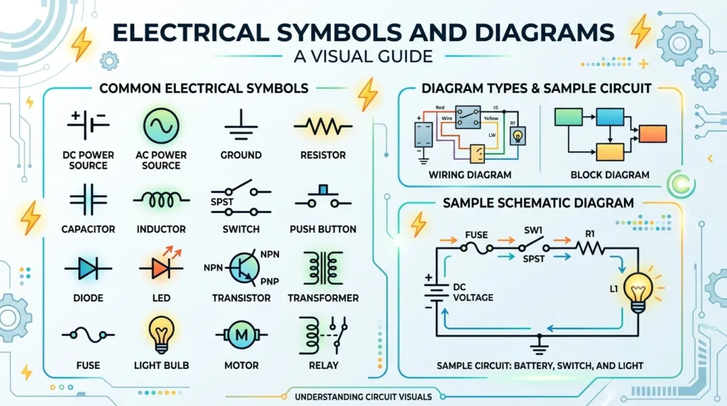
Electrical Symbols
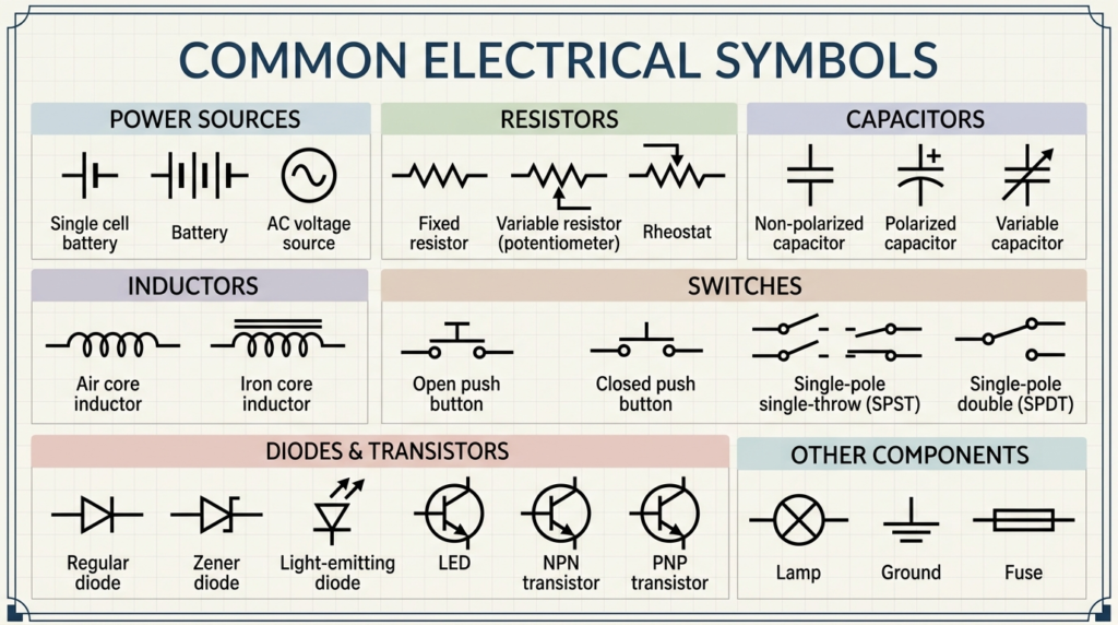
Electrical symbols are standardized graphical representations used to represent different electrical components in circuit diagrams. These symbols make it easier for engineers, technicians, and students to understand and design electrical circuits without needing to draw the actual physical components. Each electrical device such as a resistor, capacitor, switch, battery, fuse, or motor has a unique symbol that clearly represents its function in a circuit. For example, a straight line with a zigzag pattern represents a resistor, while two parallel lines of different lengths represent a battery. Electrical symbols are widely used in wiring diagrams, schematic drawings, control panels, and engineering designs. They help in simplifying complex circuits and improve communication between professionals in the electrical field. By understanding electrical symbols, beginners can easily read circuit diagrams, troubleshoot systems, and design basic electrical circuits more effectively and safely.
These represent devices like:
- Switches
- Resistors
- Capacitors
- Motors
Function: Provide a standard way to identify components
Connecting Lines
Lines represent wires or conductors.
Function: Show how components are connected
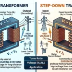
Power Source Symbols
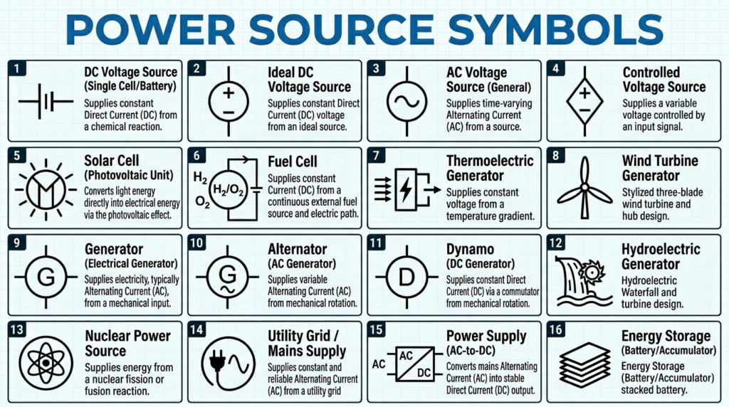
Power source symbols are electrical diagram representations used to show different types of electrical energy sources in circuit diagrams. These symbols help engineers, technicians, and students easily identify where electrical power is coming from in a circuit. Common power source symbols include battery symbols, AC supply symbols, DC supply symbols, and generator symbols. For example, a battery is represented by alternating long and short parallel lines, while an AC power source is shown as a circle with a sine wave inside it. These symbols are widely used in electrical schematics, wiring diagrams, and control system designs to clearly indicate the type and direction of electrical supply. Understanding power source symbols is very important for reading circuit diagrams correctly, designing electrical systems, and troubleshooting faults. They simplify complex electrical drawings and make communication between electrical professionals more efficient and accurate.Indicate supply like battery or AC source.
Function: Show where power comes from
Labels and Ratings
Include voltage, current, and device names.
Function: Provide additional information
Ground Symbol
Represents earth connection.
Function: Ensures safety and proper operation
6. Advantages
Here are the key electrical symbols and diagrams advantages and disadvantages, starting with benefits:
- Easy to understand complex systems
- Saves time in design and installation
- Reduces errors in wiring
- Improves communication between engineers
- Helps in troubleshooting faults
- Standardized across the world
- Supports documentation and maintenance
7. Disadvantages / Limitations
Despite their benefits, there are some limitations:
- Requires learning standard symbols
- Beginners may find diagrams confusing
- Different standards may vary slightly
- Complex diagrams can become crowded
- Misinterpretation can lead to errors
8. Applications
Electrical symbols and diagrams have wide applications in various fields.
Home Applications
- House wiring layouts
- Lighting system design
- Inverter and solar systems
Industrial Applications
- Machine control panels
- Motor circuits
- Power distribution systems
Commercial Applications
- Office electrical layouts
- Building automation systems
- HVAC system diagrams
Modern Technology
- Robotics systems
- Smart homes
- Electric vehicles
- Renewable energy systems
9. Comparison Section
Difference Between Schematic Diagram and Wiring Diagram
| Feature | Schematic Diagram | Wiring Diagram |
| Purpose | Show working principle | Show actual connections |
| Detail Level | Simple | Detailed |
| Layout | Not physical | Physical arrangement |
| Usage | Design and analysis | Installation and repair |
| Symbols | Standard symbols | Symbols + real connections |
Understanding this difference between schematic diagram and wiring diagram is essential for proper use.
10. Selection Guide
Choosing the right type of diagram depends on your purpose.
Tips for Beginners
- Use pictorial diagrams to start learning
- Move to schematic diagrams for understanding circuits
- Use wiring diagrams for practical work
- Learn common symbols first
- Practice reading simple diagrams daily
For Professionals
- Follow international standards (IEC, ANSI)
- Use software tools for complex diagrams
- Keep diagrams clean and well-labeled
- Avoid unnecessary complexity
- Update diagrams regularly
11. Common Problems & Solutions
Why can’t I understand diagrams?
Lack of symbol knowledge
Learn basic symbols first and practice regularly
What happens if symbols are used incorrectly?
Miscommunication and wrong connections
Why is my wiring not working despite correct diagram?
Incorrect interpretation
Double-check connections and labels
Are all symbols the same worldwide?
Mostly yes, but slight variations exist
How to improve diagram reading skills?
- Practice daily
- Study real circuits
- Compare diagrams with actual systems
12. Future Trends
Electrical symbols and diagrams are evolving with technology.
Digital Design Tools
- Software like CAD simplifies diagram creation
- Faster and more accurate designs
Smart Diagrams
- Interactive diagrams with real-time data
- Used in smart grids and automation
AI Integration
- Automatic diagram generation
- Error detection and optimization
IoT Systems
- Diagrams now include sensors and communication devices
Standardization Improvements
- Better global standards
- Easier collaboration across countries
13. Conclusion
Electrical symbols and diagrams are essential tools for anyone working with electrical systems. They simplify complex circuits, improve communication, and help ensure safe and accurate installations. From basic home wiring to advanced industrial systems, these diagrams play a crucial role.
Understanding the electrical symbols and diagrams working principle, types, applications, and limitations allows you to design, read, and troubleshoot systems effectively. As technology advances, diagrams are becoming more digital and intelligent, making them even more powerful.
If you are serious about electrical engineering or technical work, mastering this topic is not optional—it is necessary. Keep practicing, stay curious, and build your confidence step by step.