Imagine a technician working inside an industrial panel. A damaged cable insulation allows a live conductor to touch the metal body of the equipment. The outer body becomes energized. If someone touches it, they may receive a severe electric shock.
This dangerous situation is called an earth fault. Without proper protection, it can lead to equipment damage, fire hazards, and even loss of life.
This is why Earth Fault Protection is one of the most important safety systems in electrical engineering. Whether you are working in a small house wiring system or a large power substation, protecting against earth faults is critical.
As a junior engineer, you must clearly understand how earth faults occur, how protection systems detect them, and how they isolate the fault quickly.
In this article, you will learn:
- What Earth Fault Protection is
- Earth Fault Protection working principle
- Types of protection methods
- Earth Fault Protection applications
- Earth Fault Protection advantages and disadvantages
- The difference between earth fault and short circuit
Let us study this topic step by step in simple and practical language.
2. What is Earth Fault Protection?
Definition
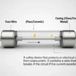
Earth Fault Protection is a safety system that detects unwanted current flowing from a live conductor to earth (ground) and disconnects the power supply to prevent damage or injury.Earth fault protection is a safety system used in electrical installations to detect leakage current flowing from electrical conductors to the earth. This type of fault usually occurs when damaged insulation, moisture, or faulty equipment allows current to escape from the normal circuit path. Earth fault protection devices continuously monitor the current balance between phase and neutral wires. If leakage current is detected beyond a safe limit, the protection system quickly disconnects the power supply to prevent electric shock, equipment damage, and fire hazards. Common earth fault protection devices include Earth Leakage Circuit Breakers (ELCBs) and Residual Current Devices (RCDs). These systems are widely used in homes, industries, power distribution systems, and commercial buildings to improve electrical safety and ensure reliable operation of equipment.
Simple Explanation
In a healthy electrical system, current flows from phase to neutral.
If insulation fails and current flows from phase to earth through metal parts or ground, it is called an earth fault.
Earth Fault Protection senses this abnormal condition and trips the circuit breaker.
Practical Example
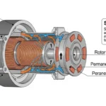
Suppose a motor winding touches its metal frame due to insulation damage.
The frame becomes live. When someone touches it, current may pass through their body to earth.
An earth fault relay detects leakage current and trips the breaker instantly.
3. Earth Fault Protection Working Principle
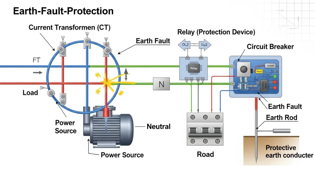
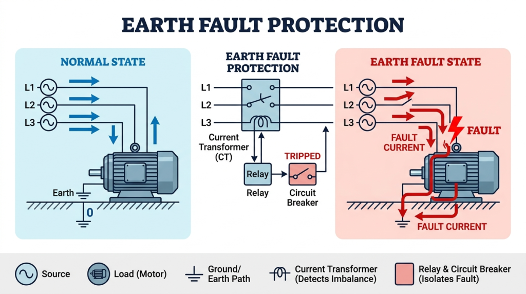
The Earth Fault Protection working principle is based on detecting imbalance or leakage current.
In a normal system:
- Current going through phase = Current returning through neutral.
In an earth fault:
- Some current leaks to earth.
- Phase current becomes higher than neutral current.
Step-by-Step Explanation
Current transformers (CTs) measure phase and neutral currents.
Under normal conditions, their sum is zero.
If leakage occurs, imbalance appears.
Relay detects this difference.
Circuit breaker trips to isolate the fault.
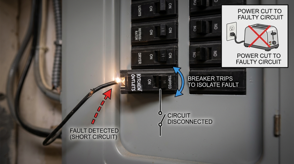
A circuit breaker trips to isolate the fault when an abnormal electrical condition such as a short circuit, overload, or earth fault occurs in the power system. The main purpose of tripping is to quickly disconnect the faulty section from the healthy electrical network to prevent damage to equipment, reduce fire risks, and maintain system safety. During a fault condition, excessive current flows through the circuit, and protective devices such as relays detect the abnormal current or voltage levels. The relay then sends a signal to the circuit breaker, causing its contacts to open automatically and interrupt the flow of current. By isolating the faulted area, the circuit breaker protects transformers, motors, generators, cables, and other electrical equipment from severe damage. Circuit breakers are widely used in homes, industries, substations, and power distribution systems because they provide fast, reliable, and reusable electrical protection. Understanding how a circuit breaker trips to isolate faults is important for electrical students, engineers, and technicians because it is a fundamental concept in electrical protection and power system stability.
Easy Analogy
Think of a water pipe system.
If water entering a tank equals water leaving, everything is fine.
If some water leaks from a hole, the output becomes less than input.
The protection system detects this leakage and shuts the valve.
4. Types / Classification
Residual Current Device (RCD)
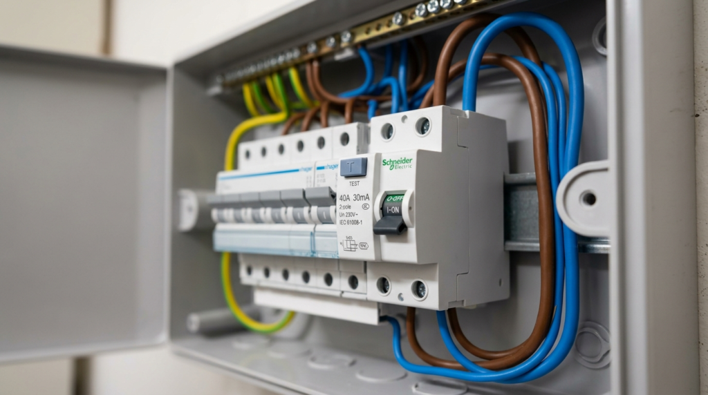
A Residual Current Device (RCD) is an electrical safety device used to protect people from electric shock and prevent electrical fires caused by leakage currents in electrical systems. It continuously monitors the current flowing through the live and neutral conductors of a circuit. Under normal conditions, the current entering through the live wire is equal to the current returning through the neutral wire. If a leakage current occurs due to damaged insulation, faulty appliances, or accidental human contact, the current becomes unbalanced. The RCD quickly detects this difference and automatically disconnects the power supply within milliseconds to reduce the risk of electric shock and equipment damage. Residual Current Devices are widely used in homes, industries, hospitals, construction sites, and commercial buildings because they provide high levels of electrical safety and protection. They are commonly installed in distribution boards along with circuit breakers and fuses. Understanding the Residual Current Device (RCD) is important for electrical students, engineers, and technicians because it plays a major role in modern electrical protection systems and human safety.
Commonly used in homes.
It trips when leakage current exceeds a safe limit (e.g., 30 mA).
Earth Fault Relay (EFR)
Used in industrial and power systems.
Works with current transformers to detect earth fault current.
Restricted Earth Fault (REF) Protection
Used for transformers and generators.
Provides sensitive protection for internal earth faults.
Directional Earth Fault Protection
Used in complex power networks.
Detects direction of fault current.
5. Main Components
Current Transformer (CT)
A Current Transformer (CT) is an essential component of an Earth Fault Protection system. Its main function is to measure the amount of current flowing through electrical conductors and provide a reduced current value that can be safely monitored by protection devices. Since power systems often carry very high currents, it is not practical or safe to connect relays and measuring instruments directly to the main conductors. The CT solves this problem by stepping down the current to a manageable level while maintaining an accurate relationship with the primary current.
In Earth Fault Protection systems, the CT continuously monitors the current flowing through the phase conductors. Under normal operating conditions, the currents remain balanced. However, if leakage current flows to the earth because of insulation failure or equipment damage, the CT detects this imbalance and sends a signal to the protection relay. This enables the system to respond quickly before the fault causes severe damage.
Functions of a Current Transformer (CT)
- Measures current flowing in electrical conductors.
- Reduces high current to a safe value for relays and meters.
- Detects abnormal current conditions.
- Supplies signals to protection devices.
- Improves the accuracy of fault detection.
- Enhances the safety of electrical systems.
Earth Fault Relay
The Earth Fault Relay is the main decision-making component in an Earth Fault Protection system. It receives signals from the current transformer and continuously compares the measured values with its preset settings. If the relay detects leakage current above the permissible limit, it interprets the condition as an earth fault and immediately initiates protective action.
Modern earth fault relays are highly sensitive and can detect even small leakage currents that might otherwise go unnoticed. This sensitivity protects equipment, prevents electrical fires, and reduces the risk of electric shock. The relay operates within milliseconds, ensuring fast fault clearance and minimizing damage to the system.
Functions of an Earth Fault Relay
- Detects earth leakage or current imbalance.
- Monitors the electrical system continuously.
- Compares measured values with preset limits.
- Sends a trip signal during fault conditions.
- Protects equipment from damage.
- Enhances personnel safety.
Circuit Breaker
A Circuit Breaker is the protective switching device that physically disconnects the faulty section of the electrical system. When the earth fault relay detects an abnormal condition, it sends a signal to the circuit breaker. The breaker then opens its contacts, interrupting the flow of electricity and isolating the affected circuit.
Unlike ordinary switches, circuit breakers are specifically designed to interrupt fault currents safely and repeatedly without damage. Their fast operation prevents overheating, equipment failure, and the spread of faults to healthy parts of the installation. Once the fault has been corrected, the breaker can usually be reset to restore power.
Functions of a Circuit Breaker
- Disconnects the faulty circuit automatically.
- Interrupts dangerous fault currents.
- Prevents damage to electrical equipment.
- Reduces the risk of electrical fires.
- Protects healthy sections of the system.
- Allows safe restoration of power after repairs.
Earthing System
The Earthing System provides a low-resistance path for fault current to flow safely into the ground. It is one of the most important safety features in any electrical installation. During an earth fault, the earthing system prevents exposed metal parts from reaching dangerous voltages that could cause electric shock.
A properly designed earthing system consists of earth electrodes, conductors, and bonding arrangements that connect equipment frames and metallic structures to the ground. This ensures that fault currents are directed away from people and equipment. Effective earthing also improves the operation of protection devices by allowing faults to be detected quickly.
Functions of an Earthing System
- Provides a safe path for fault current.
- Reduces the risk of electric shock.
- Maintains equipment at earth potential.
- Improves protective device performance.
- Prevents dangerous touch voltages.
- Enhances overall electrical safety.
Wiring and Sensors
Wiring and Sensors form the communication network of the Earth Fault Protection system. The wiring carries signals between current transformers, relays, circuit breakers, and monitoring equipment. High-quality wiring ensures that protection signals are transmitted accurately and without interruption.
Sensors provide additional information about system conditions and support advanced monitoring functions. In modern installations, sensors can track parameters such as current levels, temperature, insulation status, and fault conditions. These devices enable early fault detection and help maintenance teams respond before major failures occur.
Functions of Wiring and Sensors
- Carry control and monitoring signals.
- Connect all protection components together.
- Support accurate fault detection.
- Enable real-time system monitoring.
- Improve reliability and response time.
- Assist in preventive maintenance.
Importance of Proper Coordination
All of these components must work together correctly to ensure effective Earth Fault Protection. The current transformer detects abnormal current, the earth fault relay analyzes the condition, the circuit breaker isolates the faulty section, the earthing system safely diverts fault current, and the wiring and sensors ensure smooth communication between devices.
If any component fails to operate properly, the protection system may not respond as intended, increasing the risk of equipment damage, electrical fires, and personal injury. Therefore, regular inspection, testing, and maintenance are essential to ensure that the entire Earth Fault Protection system remains reliable, efficient, and capable of providing maximum safety.
6. Earth Fault Protection Advantages and Disadvantages
Advantages
- Prevents electric shock
- Reduces fire risk
- Protects equipment from damage
- Improves system safety
- Quick fault isolation
Real-World Benefits
- Saves human life
- Reduces downtime
- Maintains electrical reliability
7. Disadvantages / Limitations
- Sensitive settings may cause nuisance tripping
- Requires proper earthing system
- Incorrect installation reduces effectiveness
- Additional cost in large systems
Proper design and testing are essential to avoid these limitations.
8. Earth Fault Protection Applications
Home Applications
- Protection in distribution boards
- Used in bathrooms and kitchens
Industrial Applications
- Motor protection
- Transformer protection
- Generator protection
Modern Technology
- Data centers
- Solar power plants
- EV charging stations
These Earth Fault Protection applications are critical for safety and reliability.
9. Difference Between Earth Fault and Short Circuit
Many students confuse these faults. Let us compare.
| Parameter | Earth Fault | Short Circuit |
| Fault Path | Phase to earth | Phase to phase or phase to neutral |
| Current Level | Moderate to high | Very high |
| Cause | Insulation failure to ground | Direct conductor contact |
| Protection Used | Earth fault relay | Overcurrent relay |
| Risk | Shock hazard | Equipment damage |
This table clearly explains the difference between earth fault and short circuit.
10. Selection Guide
Choosing the right Earth Fault Protection system depends on:
Voltage Level
Low voltage uses RCD.
High voltage uses EFR or REF.
System Type
Solidly grounded systems need sensitive protection.
Fault Current Level
Higher systems need adjustable relays.
Tips for Beginners
- Always check earthing resistance.
- Select proper CT ratio.
- Set correct pickup current.
- Test protection regularly.
Correct selection ensures safety and reliability.
11. Common Problems & Solutions (FAQs Style)
Why does RCD trip frequently?
Possible leakage in wiring or faulty appliance.
Check insulation and connections.
What happens if earthing is poor?
Protection may not operate correctly.
Improve grounding system.
Can Earth Fault Protection prevent all accidents?
It reduces risk greatly but cannot replace safe work practices.
How to test Earth Fault Protection?
Use leakage current testing equipment and verify trip time.
12. Future Trends
The future of Earth Fault Protection is becoming smarter.
Smart Digital Relays
Provide accurate detection and remote monitoring.
IoT-Based Monitoring
Real-time fault alerts via cloud systems.
Improved Sensitivity
Advanced sensors detect very small leakage currents.
Integration with Smart Grids
Automated fault isolation improves reliability.
Modern systems focus on safety, speed, and intelligence.
13. Conclusion
Earth Fault Protection is a fundamental safety system in electrical engineering. It protects human life, equipment, and electrical installations from dangerous leakage currents.
Understanding the Earth Fault Protection working principle helps engineers design safe and reliable systems. By selecting proper relays, ensuring good earthing, and performing regular testing, faults can be detected and cleared quickly.
Always remember, electrical safety is not optional — it is mandatory. As a junior engineer, never ignore grounding systems or protection settings. A small leakage current can cause serious consequences if left unprotected.
Mastering Earth Fault Protection will strengthen your knowledge in power system protection and help you build safer electrical systems.