Imagine you turn on the lights in your house and one bulb suddenly burns out. Surprisingly, all the other lights still work perfectly. But in some older decorative light strings, if one bulb fails, the entire string stops working. Why does this happen?
The answer lies in how the electrical circuit is connected—either series or parallel.
Understanding Series vs Parallel Circuit is one of the most fundamental concepts in electrical engineering. These two connection methods determine how current flows, how voltage is distributed, and how electrical devices behave when connected together.
For electrical students, technicians, and engineers, knowing the difference between series and parallel circuit is essential. It helps in designing electrical systems, troubleshooting faults, and selecting the right circuit configuration for different applications.
In this article, you will learn the series vs parallel circuit working principle, types of circuits, components involved, series vs parallel circuit applications, advantages and disadvantages, troubleshooting tips, and future trends in circuit design.
The goal is to explain these concepts in simple, clear, and practical language, just like a senior electrical engineer teaching a junior technician.
2. What is Series vs Parallel Circuit?
A Series vs Parallel Circuit refers to two different ways electrical components such as resistors, bulbs, or devices are connected in a circuit.
Series Circuit Definition
A series circuit is a circuit where electrical components are connected one after another in a single path. The current flows through each component sequentially.
Parallel Circuit Definition
A parallel circuit is a circuit where components are connected across multiple paths. The current can flow through several branches at the same time.
Simple Explanation
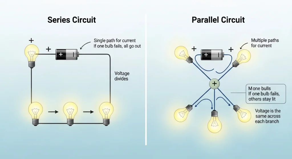
- Series circuit: One path for current flow
- Parallel circuit: Multiple paths for current flow
Practical Example
- Series circuit example: Decorative Christmas lights where bulbs are connected one after another.
- Parallel circuit example: Home wiring where appliances receive electricity independently.
Understanding these two circuit types helps engineers design safe and efficient electrical systems.
3. Series vs Parallel Circuit Working Principle
The series vs parallel circuit working principle is based on how current and voltage behave in different circuit connections.The series vs parallel circuit working principle explains how electrical components are connected and how current and voltage behave differently in each type of circuit. In a series circuit, components are connected one after another in a single path, so the same current flows through every component. If one component fails or the circuit breaks, the entire circuit stops working because there is only one path for current flow. In contrast, a parallel circuit connects components across multiple separate branches, allowing current to flow through different paths simultaneously. In a parallel circuit, each branch receives the same voltage, and if one component fails, the other branches continue operating normally. Series circuits are commonly used in simple electronic devices and decorative lighting, while parallel circuits are widely used in home wiring, industrial systems, and power distribution because they provide better reliability and independent operation of devices. The main difference between series and parallel circuits is that series circuits share current in one path, whereas parallel circuits share voltage across multiple paths. Understanding the series vs parallel circuit working principle is important for electrical students, engineers, and technicians because it forms the foundation of electrical circuit design, troubleshooting, and safe electrical installation.
Series Circuit Working Principle
In a series circuit:
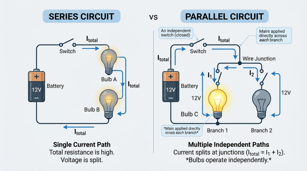
- There is only one path for current flow.
- The same current flows through all components.
- The voltage is divided across the components.
Step-by-Step Operation
- After passing through each device, current returns to the power source.
- Electrical power is supplied from the source.
- Current flows through the first component.
- It continues through all components in sequence.
Parallel Circuit Working Principle
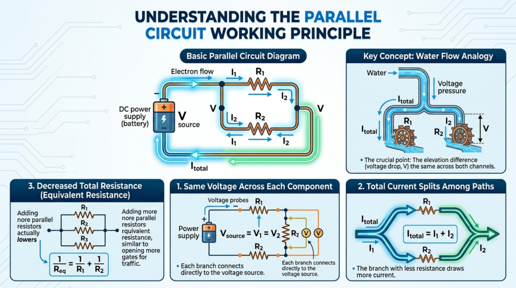
The parallel circuit working principle is based on connecting electrical components across the same voltage source through separate branches, allowing current to flow through multiple paths simultaneously. In a parallel circuit, each component receives the same supply voltage, but the current divides according to the resistance of each branch. If one branch or device stops working, the remaining branches continue operating normally because each path is independent. This is why parallel circuits are widely used in home wiring systems, lighting circuits, industrial power distribution, and electronic devices where reliable and uninterrupted operation is important. For example, in household wiring, lights and appliances are connected in parallel so that switching OFF one appliance does not affect others. The total current in a parallel circuit is equal to the sum of the currents flowing through all branches. Parallel circuits provide better flexibility, stable voltage distribution, and easy control of multiple devices. Understanding the parallel circuit working principle is important for electrical students, engineers, and technicians because it is a fundamental concept used in electrical installation, circuit design, troubleshooting, and power distribution systems.
- There are multiple paths for current flow.
- Each component receives the same voltage.
- Current divides among the branches.
Step-by-Step Operation
- Electrical power enters the circuit.
- Current splits into multiple branches.
- Each branch powers a separate component.
- Current from all branches returns to the source.
Simple Analogy
Think of water flowing through pipes.
- Series circuit: Water flows through one pipe and passes through all valves in sequence.
- Parallel circuit: Water flows through several pipes simultaneously.
4. Types / Classification of Circuits
Electrical circuits can be classified based on connection type.
Series Circuit
In a series circuit:
- Components are connected in a single line.
- Current remains constant throughout the circuit.
- Total resistance equals the sum of all resistances.
Example formula:
Total Resistance = R1 + R2 + R3
Parallel Circuit
In a parallel circuit:
- Components are connected in separate branches.
- Voltage across each component is the same.
- Total resistance decreases as more branches are added.
Example formula:
1 / Rtotal = 1/R1 + 1/R2 + 1/R3
Series-Parallel Circuit
Many practical systems use a combination of series and parallel connections.
This type of circuit is common in:
- Electronic devices
- Industrial equipment
- Power distribution systems
5. Main Components in Series and Parallel Circuits
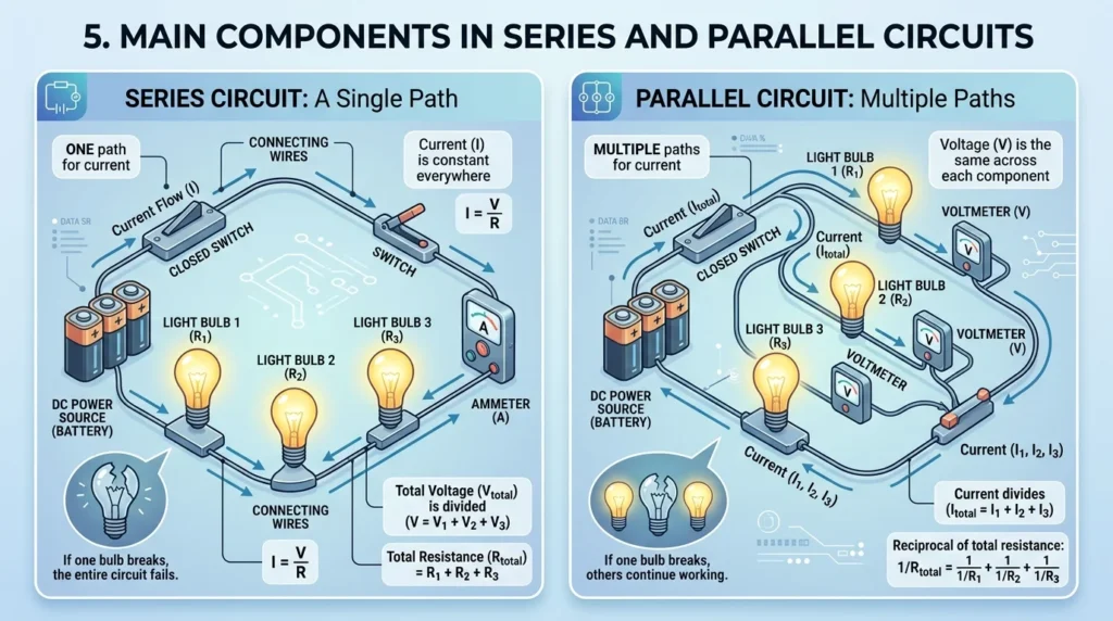
Electrical circuits include several important components.The main components in series and parallel circuits include essential electrical elements such as resistors, switches, capacitors, inductors, wires, and the power supply, which work together to control the flow of current and voltage in a circuit. In both series and parallel circuits, the power supply provides the electrical energy, while conductors or wires connect all components and allow current to flow. Resistors are used to limit or control current, switches are used to start or stop the flow of electricity, and capacitors and inductors are used in more advanced circuits for energy storage and filtering purposes. In a series circuit, these components are connected in a single path, so the same current passes through each element, making every component dependent on the others. In a parallel circuit, the same components are connected across different branches, allowing each device to operate independently while receiving the same voltage from the source. Proper selection and arrangement of these components are very important for circuit performance, safety, and efficiency. Understanding the main components in series and parallel circuits is essential for electrical students, engineers, and technicians because it helps in designing, analyzing, and troubleshooting electrical systems effectively.
Power Source
The power source provides electrical energy.
Examples:
- Batteries
- Generators
- Power supply units
Conductors (Wires)
Wires allow electrical current to flow between components.
Electrical Load
Loads consume electrical energy.
Examples:
- Bulbs
- Motors
- Heaters
Switches
Switches control the flow of electricity by opening or closing the circuit.
Protection Devices
Devices such as fuses and circuit breakers protect circuits from faults.
6. Advantages of Series vs Parallel Circuit
Understanding series vs parallel circuit advantages and disadvantages helps engineers choose the correct circuit type.
Advantages of Series Circuits
- Simple design and wiring
- Requires fewer wires
- Easy to analyze mathematically
- Useful in certain electronic devices
Advantages of Parallel Circuits
- Devices operate independently
- Failure of one component does not affect others
- Stable voltage supply
- Suitable for home electrical systems
7. Disadvantages / Limitations
Disadvantages of Series Circuits
- If one component fails, the entire circuit stops working
- Voltage is divided among devices
- Not suitable for complex systems
Disadvantages of Parallel Circuits
- Requires more wiring
- Installation may be more complex
- Higher installation cost
Despite these limitations, parallel circuits are widely used in modern electrical systems.
8. Series vs Parallel Circuit Applications
Understanding series vs parallel circuit applications is important in real-world electrical systems.
Home Electrical Wiring
Homes use parallel circuits so that appliances operate independently.
Decorative Lighting
Series circuits are sometimes used in decorative light strings.
Battery Systems
Batteries may be connected in series to increase voltage.
They may be connected in parallel to increase current capacity.
Electronic Circuits
Electronic devices often use combinations of series and parallel circuits.
Industrial Systems
Factories use parallel circuits to ensure machines operate independently.
9. Comparison: Series Circuit vs Parallel Circuit
Understanding the difference between series and parallel circuit is essential.
| Feature | Series Circuit | Parallel Circuit |
| Current Path | Single path | Multiple paths |
| Voltage Distribution | Divided across components | Same voltage across each component |
| Effect of Failure | Entire circuit stops | Other branches continue working |
| Wiring Complexity | Simple | More complex |
| Common Applications | Decorative lights | Home electrical systems |
10. Selection Guide: Choosing Between Series and Parallel Circuits
When designing circuits, engineers must choose the correct connection type.
Choose Series Circuit When
- Simple circuit design is required
- Voltage division is needed
- Low-power devices are used
Choose Parallel Circuit When
- Devices must operate independently
- Stable voltage is required
- Reliability is important
Most modern electrical systems use parallel connections.
11. Common Problems & Solutions
Why does the entire series circuit stop working?
In a series circuit, if one component fails, the current path breaks.
Solution: Replace the faulty component.
Why does voltage drop in series circuits?
Voltage divides among components based on resistance.
Solution: Design the circuit carefully.
Why do parallel circuits draw more current?
Multiple branches allow more current flow.
Solution: Use proper circuit protection devices.
How can circuit reliability be improved?
Using parallel circuits and proper protection devices improves reliability.
12. Future Trends in Circuit Design
Electrical circuit technology is continuously evolving.
Smart Electrical Systems
Modern smart homes use advanced parallel circuit systems.
Renewable Energy Systems
Solar and battery systems use both series and parallel configurations.
Intelligent Power Distribution
Smart grids are designed using advanced circuit connections.
Miniaturized Electronics
Electronic devices are using more complex combinations of series and parallel circuits.
These advancements improve system efficiency and reliability.
13. Conclusion
Series and parallel circuits are fundamental concepts in electrical engineering. They determine how electrical components are connected and how electricity flows through a system.
A series circuit provides a single path for current, while a parallel circuit provides multiple paths. Each configuration has its own advantages and limitations depending on the application.
Understanding the series vs parallel circuit working principle, series vs parallel circuit applications, and the difference between series and parallel circuit helps engineers design reliable electrical systems.
From home wiring to industrial equipment and electronic devices, these circuit types form the foundation of electrical engineering.
For students and beginners, mastering these concepts is an important step toward building strong knowledge in electrical systems and circuit design.