Imagine electricity being generated at a power station far away from your city. That electricity must travel hundreds of kilometers before reaching your home. If we send it at low voltage, huge power losses will occur, and thick expensive cables will be required. But when it reaches your home, the voltage must be safe for lights, fans, and appliances.
So how do we increase voltage for transmission and then reduce it for safe use? The answer is a transformer.
Understanding What is a Transformer? is one of the most important fundamentals in electrical engineering. Transformers are used in power plants, transmission lines, substations, industries, and even inside small electronic devices.
In this article, you will learn the transformer working principle, types, components, applications, advantages and disadvantages, comparison with similar devices, selection guide, troubleshooting tips, and future trends. I will explain everything clearly and practically, just like a senior engineer guiding a junior in a substation.
2. What is a Transformer?
Definition
A transformer is an electrical device that transfers electrical energy from one circuit to another through electromagnetic induction, usually changing voltage levels.
Simple Explanation
A transformer increases (step-up) or decreases (step-down) voltage without changing frequency.
It works only with alternating current (AC), not direct current (DC).
Practical Example
- At power stations, step-up transformers increase voltage for transmission.
- Near your home, step-down transformers reduce voltage to 230V or 120V for safe usage.
In simple words, a transformer is a voltage control device used in power systems.
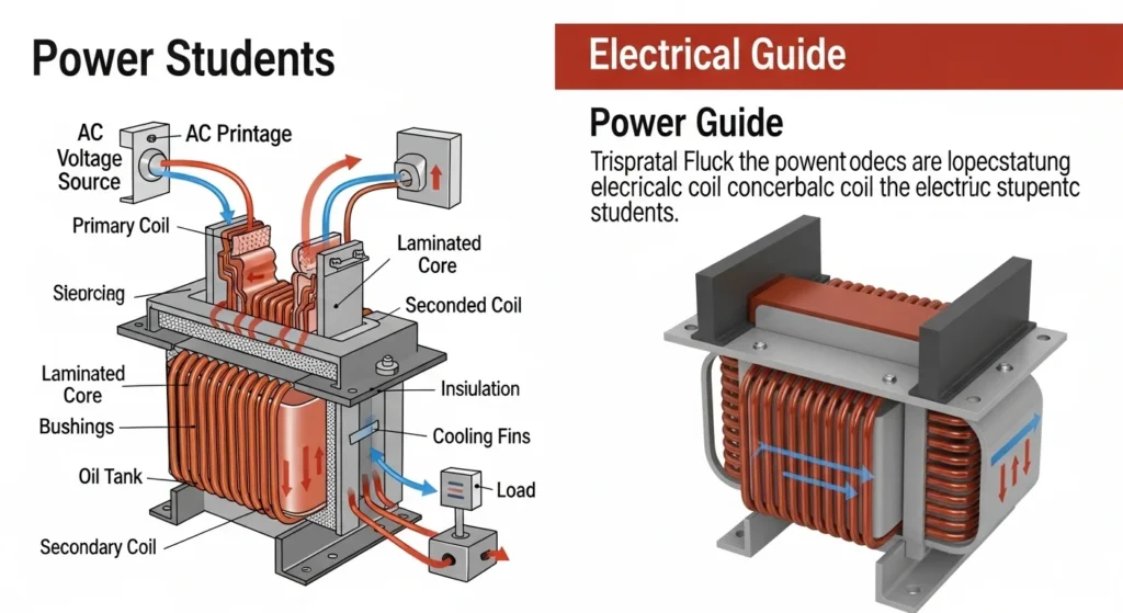
3. Transformer Working Principle
The transformer working principle is based on electromagnetic induction.
Think of it like two coils placed close together. When current flows in one coil, it creates a magnetic field. That magnetic field induces voltage in the second coil.
Step-by-Step Working
AC Supply to Primary Coil
- Alternating current flows in the primary winding.
Magnetic Field Creation
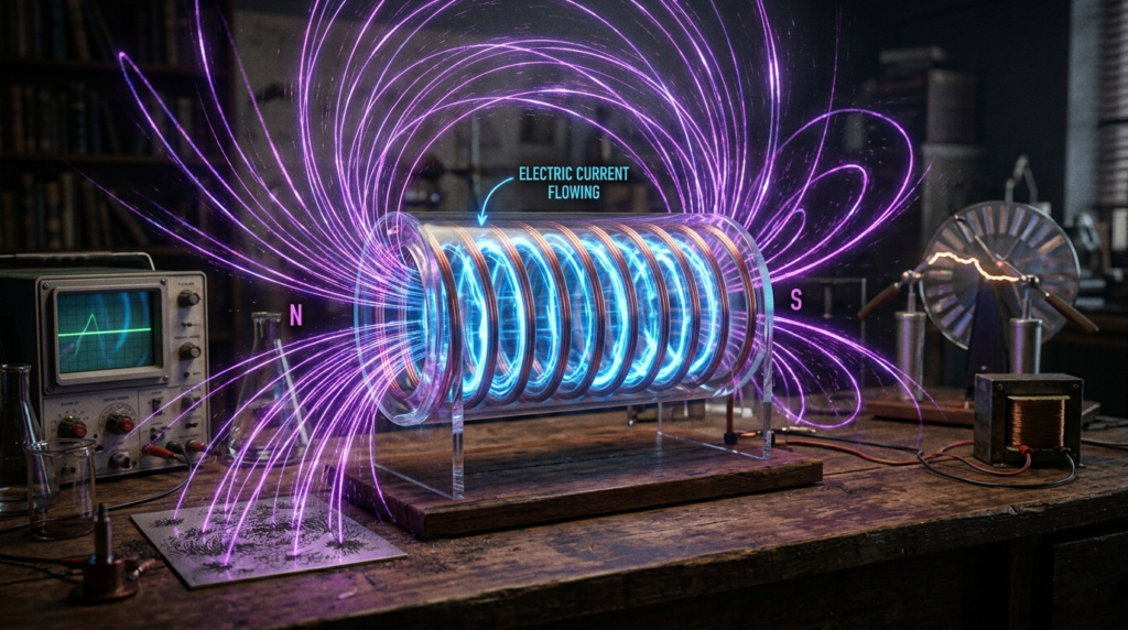
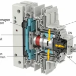
Magnetic field creation occurs when electric current flows through a conductor such as a wire, coil, or electromagnet. According to electromagnetic principles, the movement of electric charges produces a magnetic field around the conductor. The strength of the magnetic field depends on factors such as the amount of current, the number of coil turns, and the type of core material used. When current flows through a straight wire, circular magnetic lines form around it, while a coiled conductor called a solenoid produces a stronger and more concentrated magnetic field. If an iron core is placed inside the coil, the magnetic field becomes even stronger, creating an electromagnet. Magnetic field creation is the basic working principle behind many electrical devices such as motors, generators, transformers, relays, speakers, and magnetic lifting systems. Understanding magnetic field creation is important for electrical students, engineers, and technicians because it forms the foundation of electromagnetism and modern electrical machine operation.
Flux Linking Secondary Coil
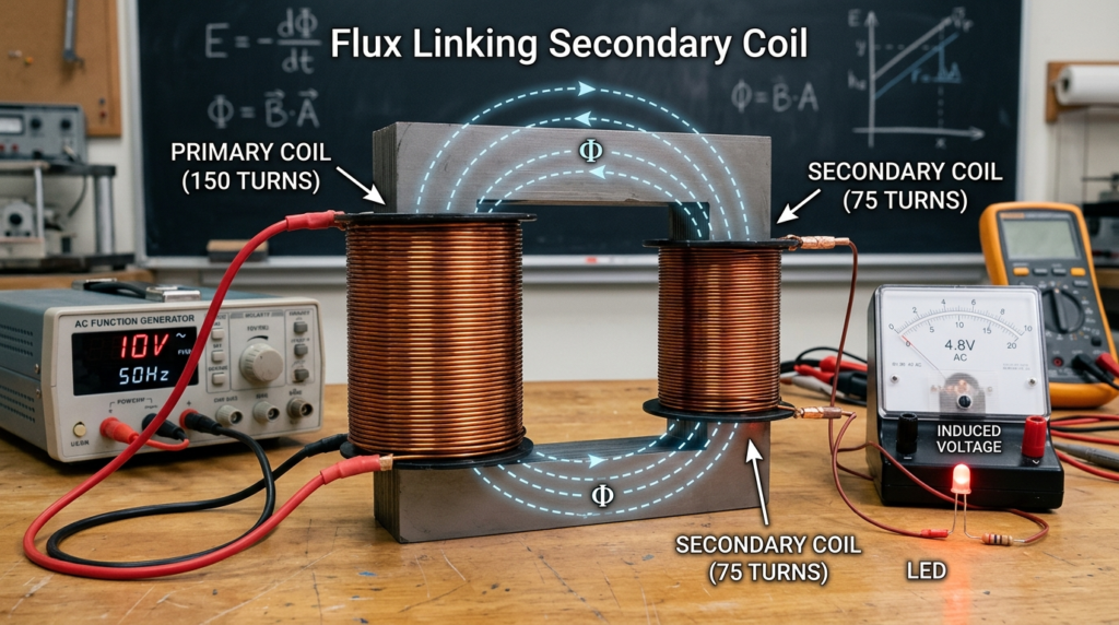
Flux linking the secondary coil is an important electromagnetic process that occurs in transformers and inductive electrical devices. When alternating current flows through the primary coil, it creates a changing magnetic field known as magnetic flux around the coil. This magnetic flux passes through the magnetic core and links with the secondary coil placed nearby. According to Faraday’s Law of Electromagnetic Induction, the changing magnetic flux linking the secondary coil induces an electromotive force (EMF) or voltage in the secondary winding. As a result, electrical energy is transferred from the primary coil to the secondary coil without direct electrical connection. The amount of induced voltage depends on the number of turns in the secondary winding and the strength of the magnetic flux. Efficient flux linking is essential for proper transformer operation, high energy transfer efficiency, and reduced power losses. Understanding flux linking in the secondary coil is important for electrical students, engineers, and technicians because it forms the basic working principle of transformers, inductors, and many electromagnetic devices used in modern electrical systems.
Induced Voltage
- Voltage is induced in the secondary winding.
Output Supply
- Load connected to secondary receives power.
Easy Analogy
Imagine two rings placed close together.
If one ring vibrates due to movement, the second ring also starts vibrating. Similarly, energy transfers from primary to secondary coil without direct connection.
Important Point
Voltage change depends on the turns ratio:
- More turns in secondary → Higher voltage
- Fewer turns in secondary → Lower voltage
This explains the basic transformer working principle.
4. Types / Classification of Transformers
Transformers are classified based on function and construction.
Step-Up Transformer
A step-up transformer is an electrical device used to increase the voltage level from the primary side to the secondary side while reducing the current proportionally. It works on the principle of electromagnetic induction, where alternating current flowing through the primary winding creates a changing magnetic flux in the transformer core. This magnetic flux links with the secondary winding and induces a higher voltage because the secondary coil contains more turns than the primary coil. Step-up transformers are widely used in power generation stations, transmission systems, renewable energy systems, and industrial applications where high voltage is required for efficient long-distance power transmission. By increasing voltage and reducing current, these transformers help minimize power losses in transmission lines. Common applications include power plants, substations, solar systems, and electronic circuits. Understanding the step-up transformer is important for electrical students, engineers, and technicians because it plays a major role in electrical power distribution and efficient energy transfer in modern electrical systems.
- Increases voltage.
- Used in power transmission.
- Secondary turns > Primary turns.
Step-Down Transformer
- Decreases voltage.
- Used in distribution systems.
- Secondary turns < Primary turns.
Power Transformer
- Used in generation and transmission.
- High voltage and high power rating.
Distribution Transformer
- Used near residential areas.
- Supplies homes and shops.
Isolation Transformer
- Provides electrical isolation.
- Used for safety in sensitive equipment.
Auto Transformer
- Single winding.
- Used for voltage regulation and motor starting.
Each type has specific transformer applications depending on system requirements.
5. Main Components of a Transformer
Understanding parts helps in proper operation and maintenance.
Core
- Made of laminated silicon steel.
- Carries magnetic flux.
Primary Winding
- Connected to input supply.
Secondary Winding
- Connected to load.
Insulation
- Prevents short circuit between windings.
Oil Tank (Oil-Filled Transformers)
- Provides cooling and insulation.
Conservator
- Stores transformer oil expansion.
Breather
- Prevents moisture entry.
Each component ensures safe and efficient transformer operation.
6. Transformer Advantages and Disadvantages
Advantages
- Efficient power transfer
- No moving parts
- Low maintenance
- Long service life
- High reliability
- Essential for long-distance transmission
These transformer advantages and disadvantages must be understood clearly.
7. Disadvantages / Limitations
- Works only on AC
- Heavy and bulky
- Initial installation cost high
- Energy losses (core and copper losses)
- Requires cooling system
Despite limitations, transformers are essential in power systems.
8. Transformer Applications
Transformer applications are found in almost every electrical system.
Power Generation Stations
Step-up transformers for transmission.
Substations
Voltage regulation and distribution.
8.3 Residential Areas
Step-down distribution transformers.
8.4 Industrial Plants
Voltage adjustment for machinery.
8.5 Electronic Devices
Adapters and chargers.
8.6 Renewable Energy Systems
Solar and wind grid connection.
Transformers are the backbone of modern electrical infrastructure.
9. Comparison Section
Difference Between Transformer and Inductor
| Feature | Transformer | Inductor |
| Purpose | Transfer power between circuits | Store energy in magnetic field |
| Windings | Two or more | Usually one |
| Voltage Change | Yes | No |
| Application | Power systems | Filters and chokes |
| Energy Transfer | Between circuits | Within same circuit |
The difference between transformer and inductor mainly lies in power transfer capability.
10. Selection Guide
Choosing the right transformer depends on:
Voltage Rating
Input and output voltage levels.
Power Rating (kVA)
Based on load demand.
Frequency
Usually 50Hz or 60Hz.
Cooling Method
Air-cooled or oil-cooled.
Installation Location
Indoor or outdoor.
Efficiency Requirement
High efficiency reduces losses.
Always calculate load properly before selection.
11. Common Problems & Solutions
Why transformer overheating?
Reason: Overload or poor cooling.
Solution: Reduce load and check cooling system.
Why humming sound increases?
Reason: Loose core laminations.
Solution: Tighten core structure.
Why oil leakage?
Reason: Damaged gasket.
Solution: Replace seal.
Q4: Why low output voltage?
Reason: Overloaded transformer.
Solution: Check load and connections.
Q5: Why insulation failure?
Reason: Moisture or aging.
Solution: Perform insulation testing.
Regular maintenance improves reliability.
12. Future Trends
Transformer technology is evolving.
Smart Transformers
Digital monitoring and remote control.
Eco-Friendly Oils
Biodegradable insulating fluids.
Compact Designs
Space-saving dry-type transformers.
Renewable Integration
Grid stability support for solar and wind.
High-Efficiency Materials
Reduced energy losses.
Future transformers will be smarter and more energy-efficient.
13. Conclusion
Understanding What is a Transformer? is essential for every electrical student and engineer. A transformer transfers electrical energy between circuits and adjusts voltage levels using electromagnetic induction. It plays a vital role in power generation, transmission, and distribution.
By learning the transformer working principle, types, applications, and the difference between transformer and inductor, you build a strong foundation in power systems. Although transformers have limitations like size and AC-only operation, their advantages make them indispensable in modern electrical networks.
Focus on correct selection, proper installation, and regular maintenance to ensure safe and efficient performance. Strong fundamentals in transformers create strong power system engineers.