Imagine turning ON a ceiling fan at home and noticing a small delay before it reaches full speed. Now think about charging your mobile phone, where energy is stored inside tiny electronic components before being used. Both situations involve two very important electrical concepts: capacitive circuits and inductive circuits. These circuits are widely used in homes, industries, power systems, communication equipment, and modern electronics.
Understanding capacitive vs inductive circuits is essential for electrical students, engineers, technicians, and beginners because these circuits affect voltage, current flow, power factor, energy storage, and electrical system performance. Incorrect understanding of these circuits can lead to poor circuit design, equipment malfunction, and energy losses.
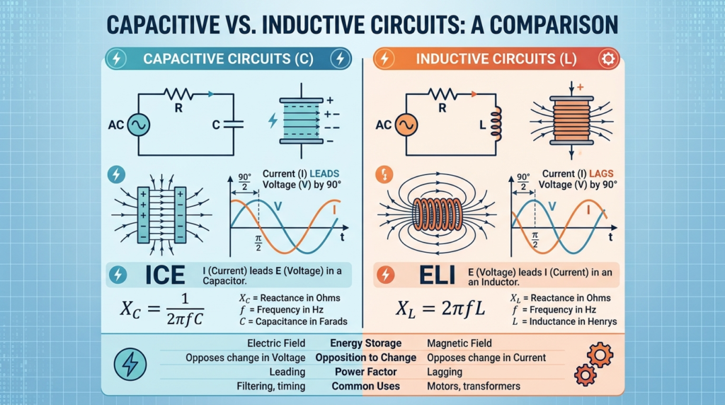
The capacitive vs inductive circuits working principle explains how capacitors and inductors behave differently when AC current flows through them. Capacitive circuits store energy in electric fields, while inductive circuits store energy in magnetic fields. Both play major roles in filters, motors, transformers, power supplies, and electronic control systems.
In this article, you will learn the difference between capacitive and inductive circuits, their working principles, types, components, advantages and disadvantages, applications, troubleshooting methods, selection guide, and future technologies in simple and easy English.
What are Capacitive vs Inductive Circuits?
Capacitive and inductive circuits are electrical circuits that mainly use capacitors or inductors to control electrical energy, voltage, current, and power flow.
A capacitive circuit mainly contains capacitors, while an inductive circuit mainly contains inductors or coils.
Simple Explanation
A capacitor stores energy in an electric field.
An inductor stores energy in a magnetic field.
Both components react differently to AC current.
Practical Example
Capacitive Circuit Example
Mobile charger circuits
Fan capacitors
Power factor correction systems
Inductive Circuit Example
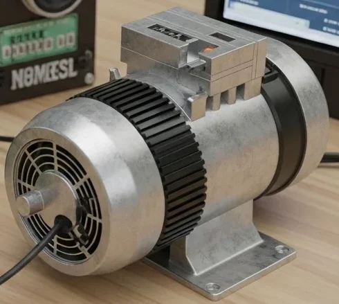
Electric motors
Transformers
Electromagnetic relays
Capacitive vs Inductive Circuits Working Principle
The capacitive vs inductive circuits working principle is based on how capacitors and inductors respond to alternating current.
Capacitive Circuit Working Principle
A capacitor stores electrical energy between two conductive plates.
Step-by-Step Process
Voltage is Applied
AC voltage is connected across the capacitor.
Electric Field Forms
An electric field develops between capacitor plates.
Charging and Discharging Starts
The capacitor continuously charges and discharges.
Current Leads Voltage
In capacitive circuits, current flows before voltage reaches maximum value.
Capacitive Reactance Formula
X_C = \frac{1}{2\pi f C}
Where:
XC = Capacitive reactance
f = Frequency
C = Capacitance
Inductive Circuit Working Principle
An inductor stores energy in a magnetic field.
Step-by-Step Process
Current Flows Through Coil
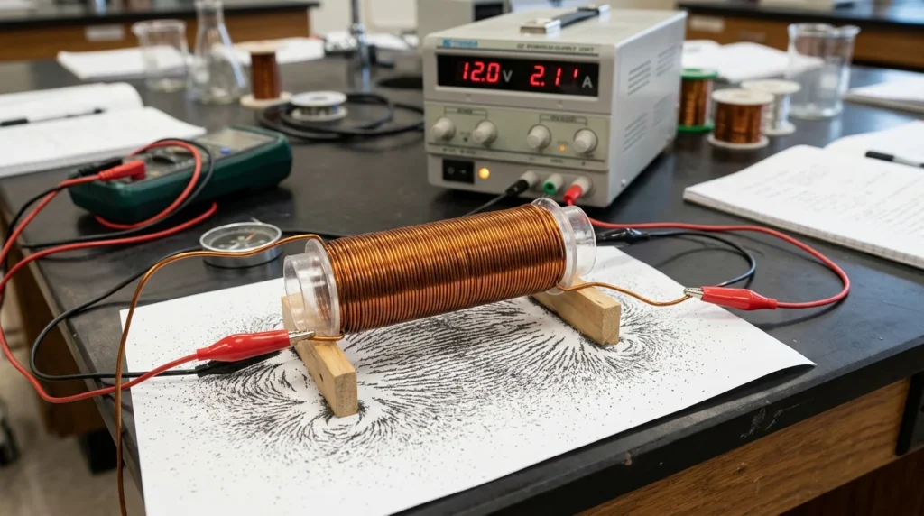
When an electric current flows through a coil of wire, it creates a magnetic field around the coil according to the principles of electromagnetism. The strength of this magnetic field depends on the amount of current flowing through the coil and the number of turns in the winding. If the coil is wound around an iron core, the magnetic field becomes much stronger because the core concentrates the magnetic flux. This magnetic field can be used to produce motion, induce voltage in nearby conductors, or operate electrical devices such as relays, solenoids, transformers, and motors. In simple words, when current flows through a coil, the coil behaves like an electromagnet and generates magnetic energy. This principle is fundamental to the operation of many electrical and electronic systems, making it an important concept for electrical students, engineers, and technicians to understand.
Electric current enters the inductor winding.
Magnetic Field Develops
The coil creates a magnetic field around itself.
Magnetic Energy is Stored
The magnetic field stores energy temporarily.
Voltage Leads Current
In inductive circuits, voltage leads current.
Inductive Reactance Formula
X_L = 2\pi f L
Where:
XL = Inductive reactance
f = Frequency
L = Inductance
Easy Analogy
Capacitor Analogy
A capacitor behaves like a water storage tank that fills and empties quickly.
Inductor Analogy
An inductor behaves like a heavy flywheel that resists sudden movement changes.
Types / Classification
Both capacitive and inductive circuits are classified into different types.
Types of Capacitive Circuits
Pure Capacitive Circuit
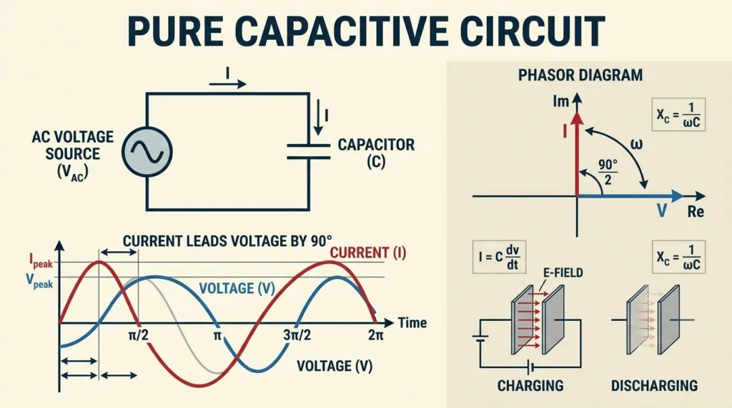
A pure capacitive circuit is an electrical circuit that contains only a capacitor connected to an AC power supply, with no resistance or inductance present. When alternating voltage is applied, the capacitor continuously charges and discharges as the voltage changes direction. As a result, current flows through the circuit even though no actual current passes through the dielectric material inside the capacitor. In a pure capacitive circuit, the current leads the voltage by 90 degrees, meaning the current reaches its maximum value before the voltage does. Because of this phase difference, the circuit consumes no real power and only exchanges reactive power with the source. In simple words, the capacitor stores electrical energy during one part of the AC cycle and releases it during another part. Pure capacitive circuits are important for understanding AC circuit behavior and are commonly used in power factor correction, filtering circuits, electronic devices, and energy storage applications.
Contains only capacitance.
Features
Current leads voltage by 90 degrees
No real power consumption
RC Circuit
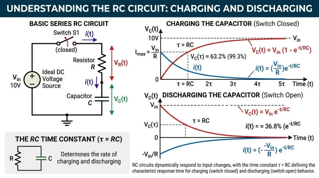
An RC circuit is an electrical circuit that consists of a resistor (R) and a capacitor (C) connected together with a voltage source. The behavior of the circuit is determined by the interaction between the resistor and the capacitor during the charging and discharging processes. When voltage is applied, the capacitor gradually charges through the resistor, causing the current to decrease over time. When the power supply is removed, the capacitor discharges through the resistor, releasing the stored energy. In an AC circuit, the resistor limits the current while the capacitor introduces a phase difference between voltage and current. In simple words, an RC circuit controls how quickly a capacitor charges and discharges, making it useful for timing, filtering, and signal processing applications. RC circuits are widely used in electronic devices, communication systems, oscillators, amplifiers, timers, and power supply filters. Understanding RC circuits is important for electrical students and technicians because they form the foundation of many electronic and electrical control systems.
Contains resistor and capacitor together.
Applications
Timing circuits
Filters
RLC Capacitive Circuit
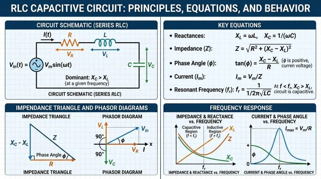
An RLC capacitive circuit is an electrical circuit that contains a resistor (R), an inductor (L), and a capacitor (C), where the capacitive reactance is greater than the inductive reactance. In this condition, the circuit behaves predominantly as a capacitive circuit. When an AC voltage is applied, the capacitor has a stronger influence on the circuit than the inductor, causing the current to lead the voltage by a certain phase angle. The resistor limits the current and dissipates power, while the capacitor and inductor store and exchange energy in the form of electric and magnetic fields. In simple words, an RLC capacitive circuit acts more like a capacitor because its capacitive effect dominates the overall circuit behavior. These circuits are commonly used in tuning circuits, filters, communication systems, power factor correction equipment, and electronic control systems. Understanding RLC capacitive circuits is important for electrical students and engineers because they help explain phase relationships, resonance phenomena, and AC circuit performance.
Contains resistor, inductor, and capacitor.
Applications
Communication systems
Resonance circuits
Types of Inductive Circuits
Pure Inductive Circuit
Contains only inductance.
Features
Voltage leads current by 90 degrees
Magnetic energy storage
RL Circuit
Contains resistor and inductor.
Applications
Motor circuits
Relay circuits
RLC Inductive Circuit
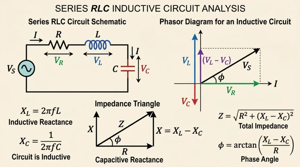
An RLC inductive circuit is an electrical circuit that consists of a resistor (R), an inductor (L), and a capacitor (C), where the inductive reactance is greater than the capacitive reactance. In this condition, the circuit behaves mainly as an inductive circuit. When an AC voltage is applied, the inductor has a stronger effect on the circuit than the capacitor, causing the current to lag behind the voltage by a certain phase angle. The resistor limits the current and dissipates electrical energy as heat, while the inductor and capacitor store and exchange energy in magnetic and electric fields. In simple words, the circuit acts more like an inductor because the inductive effect dominates its overall behavior. RLC inductive circuits are commonly used in power systems, filters, tuning networks, motor circuits, and industrial electrical equipment. Understanding RLC inductive circuits is important for electrical students and engineers because they help explain lagging power factor, phase angle relationships, resonance conditions, and the behavior of AC electrical systems.
Contains resistance, inductance, and capacitance.
Applications
Tuned circuits
Frequency filters
Main Components
Several important components are used in these circuits.
Capacitor
Stores electrical energy in electric fields.
Common Capacitor Types
Ceramic capacitor
Electrolytic capacitor
Film capacitor
Inductor
Stores energy in magnetic fields.
Common Inductor Types
Air-core inductor
Iron-core inductor
Toroidal inductor
Resistor
Controls current flow and voltage drop.
AC Power Supply
Provides alternating current for operation.
Conductors and Wiring
Carry electrical current between components.
Protection Devices
Improve circuit safety.
Examples
Fuse
Circuit breaker
Advantages
Understanding capacitive vs inductive circuits advantages and disadvantages helps improve circuit selection.
Advantages of Capacitive Circuits
Improves power factor
Reduces reactive power
Useful in filtering applications
Supports voltage stabilization
Compact design
Advantages of Inductive Circuits
Energy storage capability
Useful in transformers and motors
Controls current changes
Electromagnetic operation support
Efficient magnetic energy transfer
Disadvantages / Limitations
Both circuit types also have practical limitations.
Disadvantages of Capacitive Circuits
Sensitive to voltage spikes
Limited energy storage
Capacitor aging problems
Leakage current issues
Disadvantages of Inductive Circuits
Magnetic losses occur
Voltage spikes during switching
Large inductors require more space
Electromagnetic interference possible
Capacitive vs Inductive Circuits Applications
Capacitive and inductive circuits are used in many electrical systems.
Home Applications
Capacitive Circuit Uses
Ceiling fan capacitors
LED drivers
Home appliances
Inductive Circuit Uses
Refrigerators
Washing machines
Air conditioners
Industrial Applications
Capacitive Applications
Power factor correction
Harmonic filters
Inductive Applications
Industrial motors
Transformers
Relays
Modern Technology Applications
Wireless charging systems
Communication equipment
Renewable energy systems
Electric vehicles
Smart electronics
Comparison Section
Difference Between Capacitive and Inductive Circuits
| Feature | Capacitive Circuit | Inductive Circuit |
| Main Component | Capacitor | Inductor |
| Energy Storage | Electric field | Magnetic field |
| Current Relationship | Current leads voltage | Voltage leads current |
| Reactance Formula | 1/2πfC | 2πfL |
| Power Factor Effect | Leading | Lagging |
| Common Applications | Filters, capacitors | Motors, transformers |
| Switching Behavior | Fast response | Slower response |
| Energy Loss | Low | Magnetic losses possible |
Selection Guide
Choosing the correct circuit depends on the application.
Choose Capacitive Circuits When
Power factor correction is needed
Voltage stabilization is required
Compact filtering systems are needed
Choose Inductive Circuits When
Magnetic field operation is required
Motors or transformers are used
Current control is important
Tips for Beginners
Study Phase Relationships
Understand current and voltage phase difference carefully.
Use Proper Component Ratings
Incorrect ratings may damage components.
Avoid Overheating
Provide proper cooling and ventilation.
Follow Safety Rules
Disconnect power before handling circuits.
Learn Reactance Concepts
Reactance affects AC circuit behavior significantly.
Common Problems & Solutions
Why Is the Capacitor Overheating?
causes
Overvoltage
High frequency
Solution
Use proper capacitor rating
Improve cooling
Why Does the Inductor Produce Noise?
causes
Loose winding
Magnetic vibration
Solution
Tighten mounting
Replace damaged coil
Why Is Power Factor Poor?
causes
Excessive inductive load
Solution
Install capacitor banks
Why Does Voltage Drop Occur?
causes
High inductive reactance
Solution
Improve circuit design
Use compensation circuits
Why Does Switching Produce Sparks?
causes
Inductive voltage spikes
Solution
Use snubber circuits
Install surge protection
Future Trends
Modern electrical systems continue improving these technologies.
Smart Power Factor Correction
Automatic capacitor banks improve system efficiency.
Advanced Magnetic Materials
Modern inductors use high-efficiency magnetic cores.
Wireless Power Transfer
Capacitive and inductive coupling support wireless charging systems.
Electric Vehicle Technology
Modern EV systems use advanced inductive circuits.
Miniaturized Electronics
Smaller capacitors and inductors improve compact device design.
Renewable Energy Integration
Solar and wind systems use both capacitive and inductive technologies.
Conclusion
Capacitive and inductive circuits are fundamental parts of modern electrical and electronic systems. They control energy storage, voltage behavior, current flow, filtering, and power management in homes, industries, communication systems, and renewable energy applications.
The capacitive vs inductive circuits working principle explains how capacitors store energy in electric fields while inductors store energy in magnetic fields. Understanding the difference between capacitive and inductive circuits, their applications, advantages and disadvantages, and troubleshooting methods helps electrical students, engineers, technicians, and beginners develop strong technical knowledge and practical skills.
As electrical technology continues advancing, smart electronics, wireless charging systems, electric vehicles, renewable energy systems, and intelligent power management will increasingly depend on capacitive and inductive circuit technologies.