
Imagine you are controlling a small LED light with a switch, and at the same time, starting a large industrial motor in a factory. Both tasks involve switching circuits, but the devices used are different. For the LED, a relay might be enough, but for the motor, you need a contactor.
This real-life situation highlights the importance of understanding Contactor vs Relay. Many beginners confuse these two devices because they look similar and perform similar functions—switching electrical circuits. However, their design, capacity, and applications are quite different.
For electrical students, engineers, and technicians, knowing the difference between contactor and relay is essential for safe and efficient system design. Using the wrong device can lead to overheating, equipment damage, or even safety hazards.
In this article, you will learn the Contactor vs Relay working principle, types, components, advantages and disadvantages, applications, and how to choose the right device. By the end, you will clearly understand when to use a relay and when to use a contactor.
2. What is Contactor vs Relay?
Definition
Contactor vs Relay refers to the comparison between two electrical switching devices used to control circuits, especially in automation and power systems.
Simple Explanation
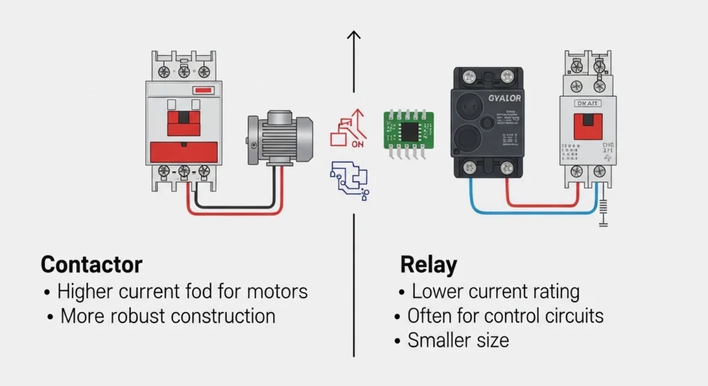
- A relay is used for low to medium power switching
- A contactor is used for high power switching
Practical Example
- Relay: Used in electronic circuits, control panels
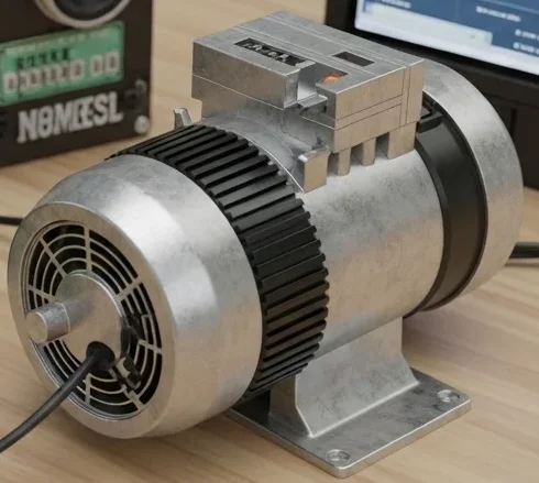
- Contactor: Used in motors, HVAC systems, industrial machines
3. Contactor vs Relay Working Principle
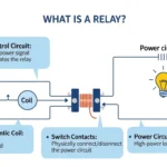
A contactor and a relay both work on the same basic principle of electromagnetic induction, but they are designed for different levels of electrical load. When a small control current is applied to the coil, it creates a magnetic field that pulls a movable armature. This movement opens or closes the electrical contacts, allowing or stopping the flow of current in another circuit. The working principle is the same in both devices, but the main difference lies in their capacity and application.
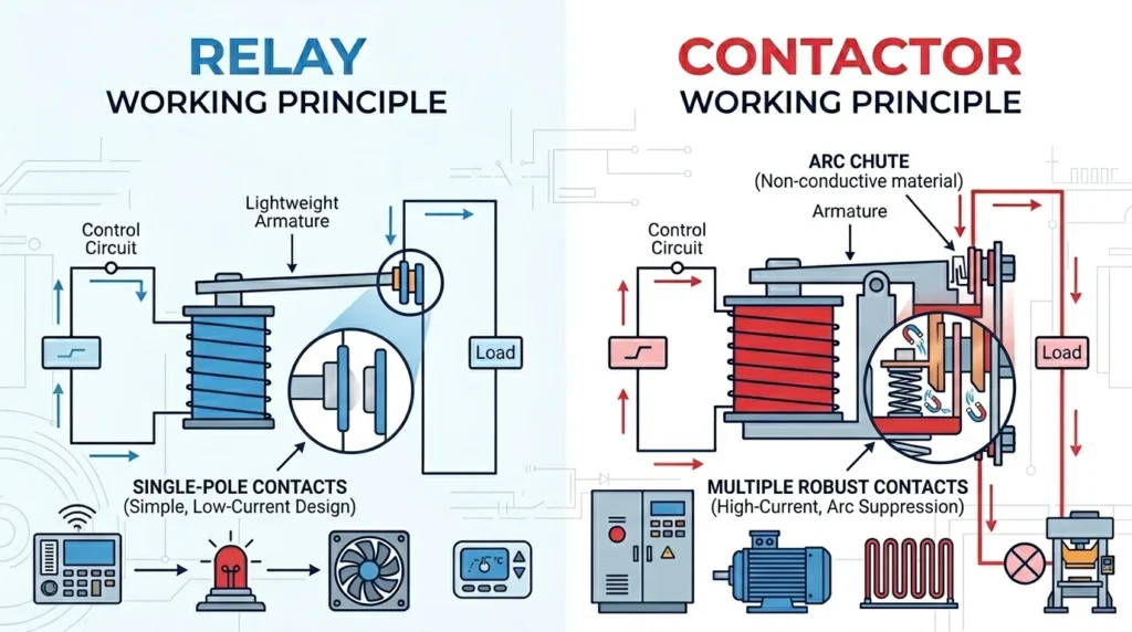
A relay is generally used for low-power circuits, such as control panels, electronic devices, and automation systems, where it switches small currents. On the other hand, a contactor is designed for high-power applications like motors, industrial machines, and heavy electrical loads. It has stronger contacts, better arc suppression, and can handle much higher currents safely. In simple terms, both work like an electromagnetic switch, but a relay is for light-duty control, while a contactor is for heavy-duty power switching.
Step-by-Step Working
Relay Working
- Current flows through coil
- Magnetic field is created
- Armature moves
- Contacts open or close
Contactor Working
- Coil is energized
- Strong magnetic field is generated
- Contacts close to allow high current flow
- Spring returns contacts when de-energized
Easy Analogy
Think of:
- Relay = Small switch controlling a lamp
- Contactor = Heavy-duty switch controlling a large machine
Key Difference
- Relay handles control signals
- Contactor handles power circuits
4. Types / Classification
Types of Relays
Electromechanical Relay
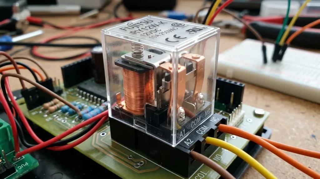
An electromechanical relay is an electrical switching device that uses an electromagnetic coil to open or close electrical contacts. When a small current flows through the coil, it creates a magnetic field that pulls a movable armature, which then changes the position of the contacts. This allows the relay to control a high-power circuit using a low-power signal, making it very useful in automation and control systems. Electromechanical relays are widely used in electrical panels, protection systems, and industrial machines because they provide reliable isolation between control and power circuits. They are simple in design, cost-effective, and easy to replace, but they have moving parts, which means they can wear out over time.
- Uses moving parts
- Common in control systems
Solid State Relay
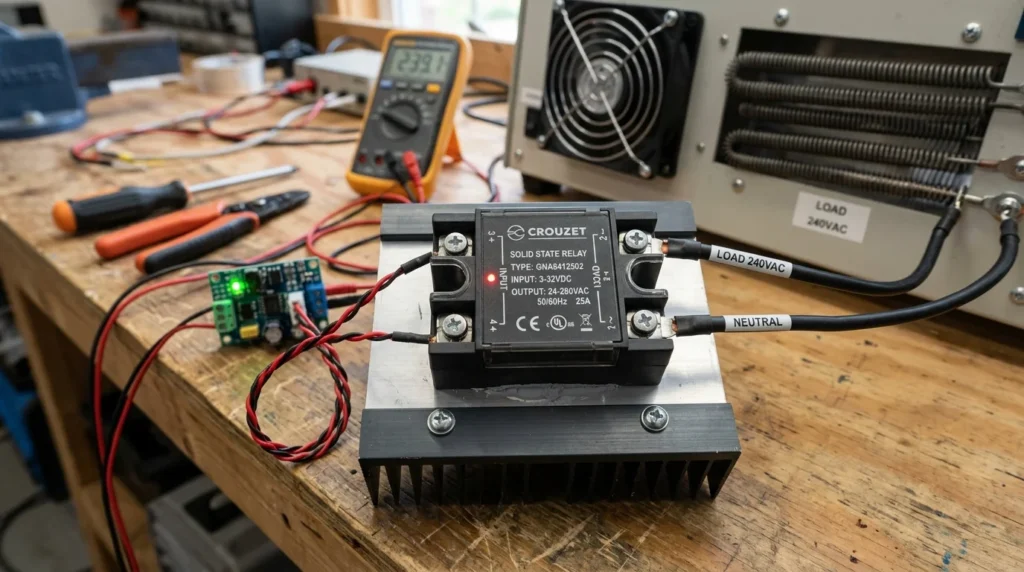
A solid state relay (SSR) is an electronic switching device that performs the same function as a traditional relay but without any moving mechanical parts. Instead of an electromagnetic coil and physical contacts, it uses semiconductor components such as thyristors, triacs, or transistors to switch electrical loads. When a small input voltage is applied, the internal electronic circuit activates and allows current to flow through the output side. Solid state relays are widely used in industrial automation, temperature control systems, and high-speed switching applications because they operate silently, respond very quickly, and have a long service life. Since there is no mechanical wear, they require very little maintenance, but they can generate heat and are usually more expensive than electromechanical relays.
- No moving parts
- Fast switching
Types of Contactors
AC Contactor
- Used in AC systems
- Common in motors
DC Contactor
- Used in DC circuits
- Requires special design
Magnetic Contactor
- Uses electromagnetic coil
- Widely used in industries
5. Main Components
Relay Components
- Coil
- Armature
- Contacts (NO/NC)
- Spring
Contactor Components
- Coil
- Power contacts
- Auxiliary contacts
- Arc chute (important feature)
- Enclosure
Function Difference
- Relay: Light-duty switching
- Contactor: Heavy-duty switching with arc control
6. Contactor vs Relay Advantages
Relay Advantages
- Compact size
- Low cost
- Suitable for low-power circuits
- Easy to use
Contactor Advantages
- Handles high current loads
- Designed for frequent switching
- Longer lifespan in heavy-duty use
- Better safety features
7. Contactor vs Relay Disadvantages / Limitations
Relay Limitations
- Cannot handle high current
- Contacts wear out quickly
- Not suitable for motors
Contactor Limitations
- Larger size
- More expensive
- Requires proper installation
- Consumes more coil power
8. Contactor vs Relay Applications
Relay Applications
- Electronic circuits
- Control panels
- Signal switching
- Automation systems
Contactor Applications
- Motor control
- Industrial machinery
- HVAC systems
- Power distribution
Modern Applications
- Smart automation systems
- PLC-based control
- Renewable energy systems
9. Comparison Section
Difference Between Contactor and Relay
| Feature | Relay | Contactor |
| Current Capacity | Low to medium | High |
| Application | Control circuits | Power circuits |
| Size | Small | Large |
| Switching Frequency | Moderate | High |
| Arc Control | Not available | Available |
| Cost | Low | Higher |
| Durability | Lower | Higher |
10. Selection Guide
Choosing between relay and contactor depends on application.
Use Relay When
- Low current switching
- Electronic circuits
- Control signals
Use Contactor When
- High current loads
- Motor control
- Industrial applications
Tips for Beginners
- Always check current rating
- Consider load type
- Use contactor for safety in high-power systems
- Never overload a relay
11. Common Problems & Solutions
Relay burning out?
Problem: Overloading
Solution: Use proper rating
Contactor not working?
Problem: Coil failure
Solution: Check voltage supply
Contacts getting damaged?
Problem: Frequent switching
Solution: Use proper device
Noise during operation?
Problem: Mechanical movement
Solution: Use better quality device
System overheating?
Problem: Wrong device selection
Solution: Replace with suitable contactor
12. Future Trends
Electrical switching devices are evolving.
New Developments
- Smart contactors
- Solid state relays
- IoT-based control systems
- Energy-efficient designs
Industry Direction
- Automation and smart grids
- Improved safety systems
- Digital control integration
What to Expect
- Faster switching devices
- Longer lifespan
- Reduced maintenance
13. Conclusion
Understanding Contactor vs Relay is crucial for selecting the right switching device in electrical systems. While both devices operate on similar principles, their applications and capabilities are very different.
Relays are ideal for low-power control circuits, whereas contactors are designed for high-power applications like motor control. Knowing the difference between contactor and relay, along with their advantages and disadvantages, helps prevent system failures and ensures safety.
As an electrical professional or learner, always choose the correct device based on load requirements and application. This knowledge will help you design efficient, safe, and reliable electrical systems.