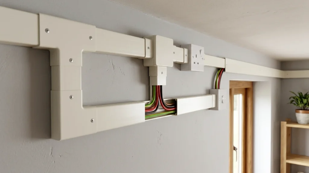
Imagine wiring a small house, office, or workshop where electrical cables need protection while remaining easy to inspect and maintain. Instead of hiding the wires inside walls, electricians install them neatly inside protective channels fixed on walls and ceilings. These channels protect the conductors from damage while keeping the wiring organized and accessible. This wiring method is known as Casing Capping Wiring.
Before modern PVC conduit systems became popular, casing capping wiring was one of the most widely used wiring methods in residential and commercial buildings. Even today, it is still used in certain applications because of its simple installation, low maintenance requirements, and ease of inspection.
For electrical students, engineers, technicians, and beginners, understanding casing capping wiring is important because it helps build knowledge of traditional wiring methods and electrical installation practices. Learning about this system also improves understanding of cable protection, safety requirements, and wiring layouts.
In this article, you will learn what casing capping wiring is, the casing capping wiring working principle, types, components, applications, advantages and disadvantages, troubleshooting methods, selection guidelines, and future industry trends.
What is Casing Capping Wiring?
Casing capping wiring is a surface wiring method in which insulated conductors are placed inside a rectangular casing and covered with a protective cap known as capping.
In simple words, the wires run through a protective channel mounted on walls or ceilings, and a removable cover protects them from dust, moisture, and mechanical damage.
The casing acts as the base structure, while the capping serves as the protective cover.
Practical Example
In a workshop or temporary office setup, electrical wires may be installed inside PVC casing channels mounted on walls. The protective capping keeps the conductors secure while allowing easy access for repairs or modifications.
Casing Capping Wiring Working Principle
The casing capping wiring working principle is based on providing a protected pathway for electrical conductors while ensuring safe power distribution throughout the installation.
Simple Analogy
Think of a road tunnel that protects vehicles from external weather conditions.
Similarly, the casing protects electrical wires from physical damage and environmental factors.
Step-by-Step Casing Capping Wiring Working Principle
Casing Installation
The casing is mounted on walls or ceilings using screws and supports.
Wire Placement
Electrical conductors are placed inside the casing.
Circuit Routing
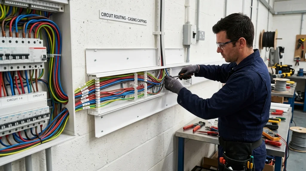
Circuit routing is the process of planning and arranging the path of electrical wires or printed circuit board (PCB) traces to ensure efficient and safe transmission of electrical signals. Proper circuit routing helps reduce signal interference, voltage loss, and the risk of short circuits while improving the overall performance and reliability of the electrical system. It also makes installation, troubleshooting, and maintenance easier. Good circuit routing follows standard electrical codes and design practices to ensure safety, efficiency, and long-term operation.
The wires are routed to switches, sockets, lights, and electrical loads.
Capping Installation
The protective cap is fitted over the casing.
Electrical Connections
Wires are connected to devices and distribution points.
Power Distribution
Electricity flows through the protected conductors.
Inspection and Maintenance
The capping can be removed easily for inspection and repairs.
Key Features of Casing Capping Wiring Working Principle
- Organized cable routing
- Easy maintenance
- Mechanical protection
- Accessible wiring
- Safe electrical distribution
Types / Classification
Casing capping wiring systems can be classified according to material and construction.
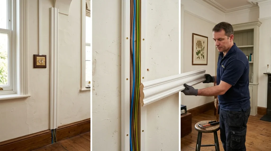
Wooden Casing Capping Wiring
Wooden casing capping wiring is a traditional wiring system in which insulated electrical wires are laid inside a wooden casing and covered with a wooden capping for protection. The casing is fixed to the wall or ceiling, and the capping is placed over it to keep the wires secure and organized. This method provides mechanical protection, gives a neat appearance, and allows easy inspection and maintenance of the wiring. Although it was widely used in the past, wooden casing capping wiring has largely been replaced by PVC conduit and other modern wiring systems because they offer better durability, fire resistance, and moisture protection.
One of the oldest wiring methods.
Features
- Wooden casing and capping
- Traditional installation
Applications
- Historical buildings
- Educational demonstrations
PVC Casing Capping Wiring
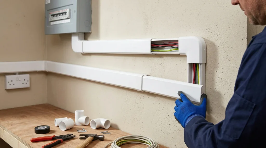
PVC casing capping wiring is a modern wiring system in which insulated electrical wires are placed inside a PVC (Polyvinyl Chloride) casing and covered with a matching PVC capping. The casing is fixed to the wall or ceiling, while the capping protects the wires from dust, moisture, and mechanical damage. This wiring method provides a neat appearance, is easy to install and maintain, and offers good electrical insulation. Due to its durability, low cost, and resistance to corrosion and fire, PVC casing capping wiring is widely used in residential, commercial, and industrial electrical installations.
The most common modern version.
Features
- Lightweight
- Moisture resistant
Applications
- Homes
- Offices
- Commercial buildings
Single Channel Casing Capping
Contains one wire compartment.
Features
- Simple design
Applications
- Small circuits
Multi-Channel Casing Capping
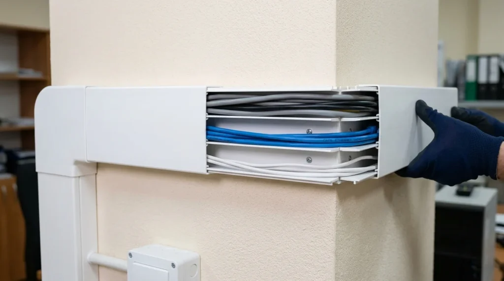
Multi-channel casing capping is an advanced wiring system that contains two or more separate channels within a single PVC casing to carry different groups of electrical wires. These channels keep power, lighting, communication, and data cables separated, reducing interference and making the wiring more organized. The capping securely covers the channels, protecting the wires from dust, moisture, and mechanical damage. This system is easy to install, simplifies maintenance, and is widely used in homes, offices, commercial buildings, and industrial installations where multiple electrical circuits are required.
Contains multiple compartments.
Features
- Better circuit organization
Applications
- Large installations
Surface Mounted Casing Capping
Installed directly on wall surfaces.
Features
- Easy access
Applications
- Workshops
- Temporary installations
Main Components
Understanding the main components helps explain how casing capping wiring functions.
Casing
The base channel that holds conductors.
Function
- Supports electrical wires
Capping
Protective cover placed over the casing.
Function
- Protects conductors
Insulated Conductors
Electrical wires carrying current.
Function
- Power transmission
Junction Box
Connection point for circuits.
Function
- Wire branching
Fasteners
Screws and clips used for mounting.
Function
- Secure installation
Switches
Control electrical circuits.
Function
- Switching operation
Sockets
Provide power outlets.
Function
- Supply electricity to loads
Distribution Board
Power distribution center.
Function
- Circuit protection and control
Advantages
Understanding casing capping wiring advantages and disadvantages helps determine its suitability.
Advantages of Casing Capping Wiring
- Easy installation
- Low maintenance cost
- Simple inspection
- Good wire protection
- Easy fault detection
- Flexible modifications
- Organized appearance
- Cost-effective solution
Real-World Benefits
Easy Troubleshooting
Wires remain accessible for inspection.
Quick Installation
Requires less construction work.
Flexible Expansion
Additional circuits can be added easily.
Reduced Maintenance Time
Repairs can be completed quickly.
Disadvantages / Limitations
Despite its benefits, casing capping wiring has some limitations.
Casing Capping Wiring Advantages and Disadvantages
Disadvantages
- Less attractive appearance
- Not suitable for harsh environments
- Limited mechanical strength
- Can occupy wall space
- Wooden systems may be affected by moisture
Practical Limitations
Exposure Risk
Surface-mounted installations may be damaged accidentally.
Aging Materials
Older casing materials may deteriorate over time.
Aesthetic Concerns
Concealed wiring often provides a cleaner appearance.
Casing Capping Wiring Applications
Casing capping wiring applications are still found in various installations.
Residential Applications
- Houses
- Apartments
- Temporary wiring systems
Commercial Applications
- Offices
- Shops
- Retail stores
Educational Applications
- Electrical laboratories
- Training centers
Industrial Applications
- Small workshops
- Maintenance facilities
Temporary Installations
- Construction sites
- Exhibition halls
Renovation Projects
- Buildings where concealed wiring is impractical
Casing capping wiring applications remain useful where accessibility and simplicity are important.
Comparison Section
Difference Between Casing Capping Wiring and Conduit Wiring
| Feature | Casing Capping Wiring | Conduit Wiring |
| Installation Cost | Lower | Higher |
| Appearance | Surface Mounted | Concealed or Surface |
| Maintenance | Easy | Moderate |
| Protection Level | Moderate | High |
| Expansion | Easy | More Difficult |
| Durability | Moderate | High |
| Inspection | Easy | Limited |
| Common Use | Small Installations | Modern Buildings |
Understanding the difference between conduit wiring and casing capping wiring helps engineers select the most appropriate wiring method.
Selection Guide
Choosing the right casing capping wiring system depends on several factors.
Installation Environment
Evaluate indoor and outdoor conditions.
Load Requirements
Determine current carrying needs.
Material Selection
Choose PVC or other suitable materials.
Future Expansion
Allow space for additional circuits.
Budget Considerations
Compare installation costs with alternatives.
Tips for Beginners
- Use high-quality casing materials.
- Avoid overfilling channels.
- Follow electrical safety standards.
- Provide proper circuit labeling.
- Perform regular inspections.
Common Problems & Solutions
Loose Capping
Causes
- Poor installation
- Aging materials
Solution
- Replace damaged sections
Wire Overheating
Causes
- Overloaded circuits
Solution
- Reduce load or increase conductor size
Cracked Casing
Causes
- Mechanical damage
Solution
- Replace damaged components
Loose Connections
Causes
- Vibration
- Improper tightening
Solution
- Retighten electrical connections
Moisture Entry
Causes
- Damaged covers
Solution
- Seal or replace affected sections
Future Trends
Although modern wiring systems dominate new construction, casing capping technology continues improving.
Advanced PVC Materials
Improved durability and fire resistance.
Smart Cable Management Systems
Better organization and monitoring capabilities.
Modular Wiring Designs
Faster installation and expansion.
Enhanced Safety Features
Improved insulation and protection materials.
Sustainable Materials
Environmentally friendly manufacturing processes.
Integrated Data and Power Channels
Support for modern communication systems.
The future of casing capping wiring applications is expected to focus on improved materials, safety enhancements, and better cable management solutions.
Conclusion
Casing capping wiring is a traditional yet practical wiring method that provides a safe and organized pathway for electrical conductors. By protecting wires inside a casing and covering them with a removable cap, the system allows easy installation, inspection, maintenance, and future modifications. Although modern conduit wiring has become more common, casing capping wiring remains useful in residential, commercial, educational, and temporary installations.
This article explained the casing capping wiring working principle, types, components, applications, advantages and disadvantages, troubleshooting methods, and future developments in simple and practical language. You also learned the difference between conduit wiring and casing capping wiring and how to select the appropriate system based on installation requirements.
For electrical students, engineers, technicians, and beginners, understanding casing capping wiring provides valuable knowledge of electrical installation techniques and cable management practices. Mastering this wiring method helps build a strong foundation in electrical engineering and practical wiring design.