Imagine entering a room on a hot summer day and turning ON the ceiling fan for instant comfort. Most people use ceiling fans daily without thinking about the electrical wiring working behind the scenes. A properly wired ceiling fan provides safe operation, smooth performance, and efficient airflow in homes, offices, schools, and commercial buildings.
Understanding the ceiling fan wiring diagram is very important for electrical students, technicians, engineers, and beginners. Correct wiring helps prevent electrical faults, short circuits, overheating, and fan damage. It also improves installation safety and troubleshooting skills. Whether you are installing a new fan, replacing an old one, or repairing a faulty connection, learning fan wiring basics is essential.
The ceiling fan wiring diagram working principle explains how electricity flows from the power supply through switches, regulators, capacitors, and motor windings to rotate the fan blades. With proper knowledge, even beginners can understand how different wiring systems operate safely.
In this article, you will learn everything about ceiling fan wiring diagrams, including working principles, types, components, advantages and disadvantages, applications, comparison, troubleshooting methods, selection tips, and future trends in fan wiring technology.
What is a Ceiling Fan Wiring Diagram?
A ceiling fan wiring diagram is a visual representation that shows how electrical wires are connected inside a ceiling fan circuit. It helps electricians, technicians, and students understand the proper connection between power supply wires, switches, capacitors, regulators, and the fan motor.
In simple words, a wiring diagram acts like a road map for electricity.
It shows:
Where wires should connect
How current flows
Which components control the fan
Simple Explanation
A ceiling fan wiring diagram helps users install and repair ceiling fans safely by showing correct wire connections.
Without a proper wiring diagram, incorrect wiring may cause:
Fan malfunction
Electric shock
Circuit damage
Overheating
Practical Example
In a home ceiling fan system:
The phase wire passes through the switch and regulator
Neutral wire connects directly to the fan
Capacitor helps start and run the motor
The wiring diagram clearly shows these connections.
Ceiling Fan Wiring Diagram Working Principle
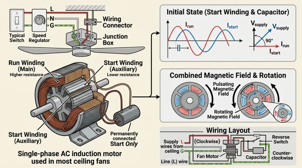
A ceiling fan wiring system consists of a power supply, switch, regulator, capacitor, and fan motor. The live wire from the power supply passes through the switch and regulator before reaching the fan, while the neutral wire is connected directly to the motor. The capacitor is connected with the motor to provide the starting torque required to rotate the fan. When the switch is turned on, electric current flows through the circuit, and the capacitor creates a phase difference between the motor windings. This produces a rotating magnetic field that starts and continuously drives the fan blades. The regulator controls the speed of the fan by adjusting the voltage supplied to the motor, ensuring smooth and efficient operation.
The ceiling fan wiring diagram working principle is based on controlling electrical current flow to operate the fan motor.
Step-by-Step Working Process
Power Supply Enters Circuit
Electrical power comes from the main supply through phase and neutral wires.
Switch Controls Current
The switch turns the fan ON or OFF by opening or closing the circuit.
Regulator Controls Speed
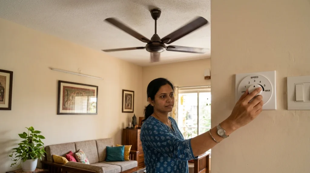
A fan regulator is an electrical device used to control the speed of a ceiling fan by regulating the voltage supplied to the motor. When the regulator setting is increased or decreased, it changes the amount of electrical power reaching the fan, causing the motor to rotate faster or slower. Modern electronic regulators provide smooth and efficient speed control while reducing power consumption and heat generation. Fan regulators improve comfort, save energy, and ensure reliable operation of the ceiling fan.
The regulator adjusts voltage or current to control fan speed.
Capacitor Creates Phase Shift
The capacitor helps create a rotating magnetic field inside the motor.
This allows the motor to start rotating smoothly.
Motor Rotates Fan Blades
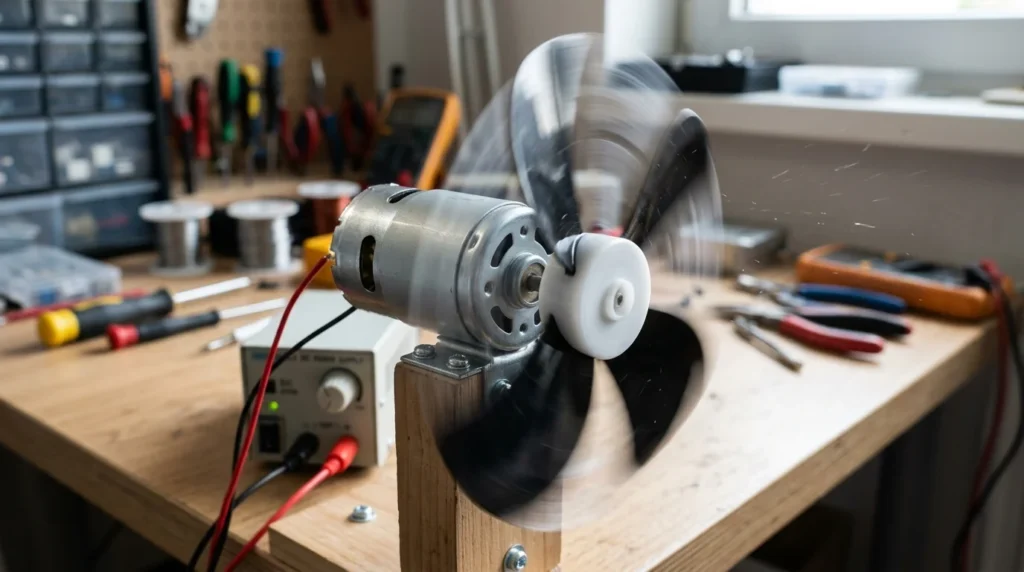
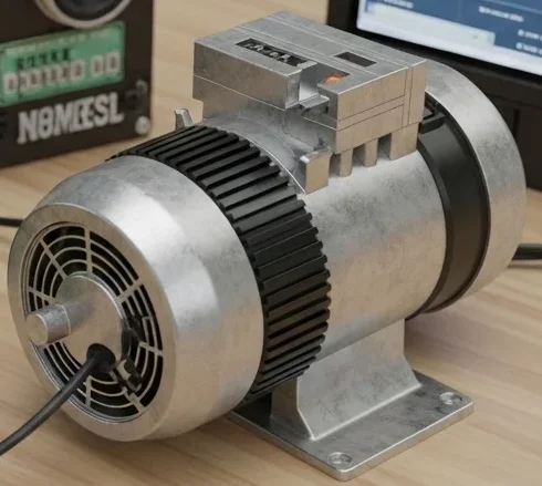
The electric motor is the main component of a ceiling fan that rotates the fan blades. When electric current flows through the motor windings, a rotating magnetic field is produced, causing the rotor to spin. The rotating motor shaft is connected directly to the fan blades, which move the surrounding air and create a cooling effect. The speed of the motor, controlled by the fan regulator, determines how fast the blades rotate and how much airflow the fan produces.
The motor converts electrical energy into mechanical energy.
The blades rotate and circulate air.
Easy Analogy
Think of a ceiling fan like a water wheel:
Electricity acts like flowing water
The switch acts like a gate
The regulator controls flow speed
The motor rotates like the wheel
Basic Electrical Flow
Simple Fan Wiring Path
Power Supply → Switch → Regulator → Capacitor → Fan Motor
Types / Classification
Different ceiling fan wiring systems are used depending on installation requirements.
Single Switch Ceiling Fan Wiring
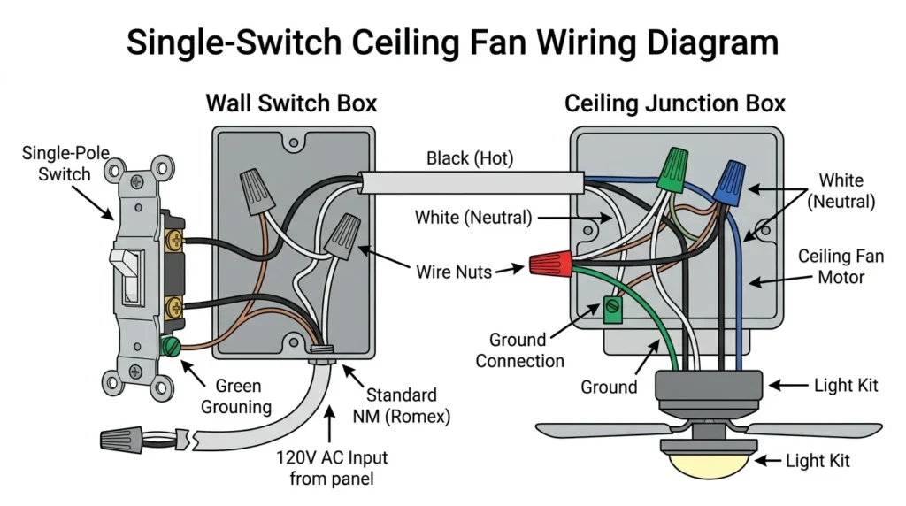
A single switch ceiling fan wiring system is the simplest method of connecting a ceiling fan to the electrical supply. In this wiring arrangement, the live (phase) wire passes through a single switch before reaching the fan motor, while the neutral wire is connected directly to the fan. When the switch is turned on, electric current flows through the circuit, allowing the motor to operate and rotate the fan blades. Turning the switch off disconnects the power supply and stops the fan. This wiring method is commonly used in homes because it is simple, reliable, and easy to install.
This is the simplest wiring system.
Features
One switch controls the fan
Basic household setup
Easy installation
Applications
Bedrooms
Small rooms
Simple home wiring
Fan with Regulator Wiring
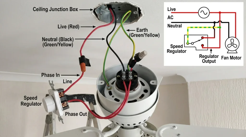
A fan with regulator wiring system includes a power supply, a switch, a fan regulator, and the ceiling fan. In this wiring arrangement, the live (phase) wire passes through the switch and then the regulator before reaching the fan motor, while the neutral wire is connected directly to the fan. When the switch is turned on, the regulator controls the voltage supplied to the motor, allowing the fan speed to be adjusted from low to high. This wiring method provides smooth speed control, improves comfort, reduces energy consumption, and ensures efficient operation of the ceiling fan.
This system includes a speed regulator.
Features
Adjustable speed control
Better comfort
Energy management
Applications
Homes
Offices
Classrooms
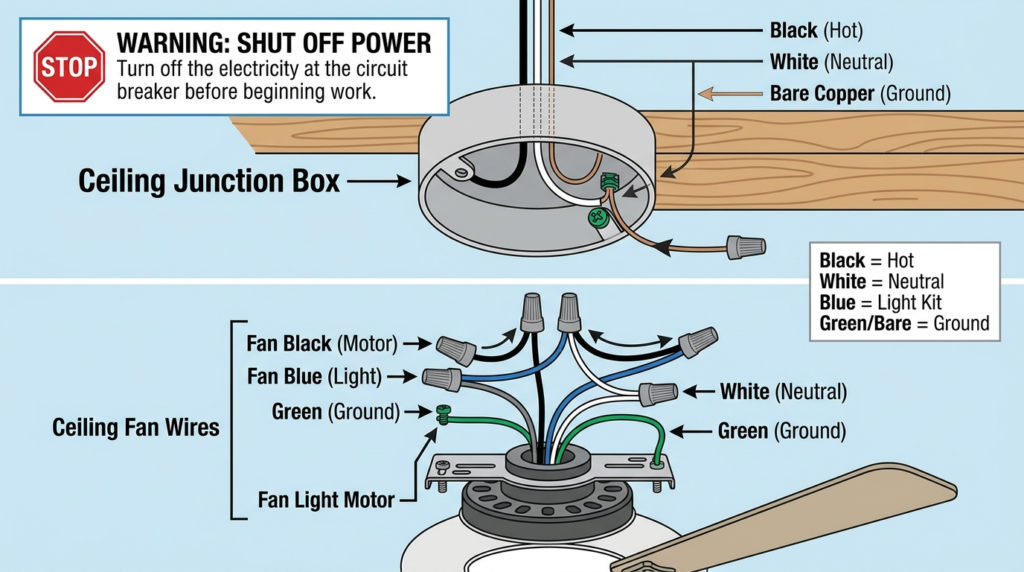
Ceiling Fan with Light Wiring
A combined fan and lighting system.
Features
One unit for fan and light
Separate or combined switches
Applications
Bedrooms
Living rooms
Hotels
Remote-Controlled Ceiling Fan Wiring
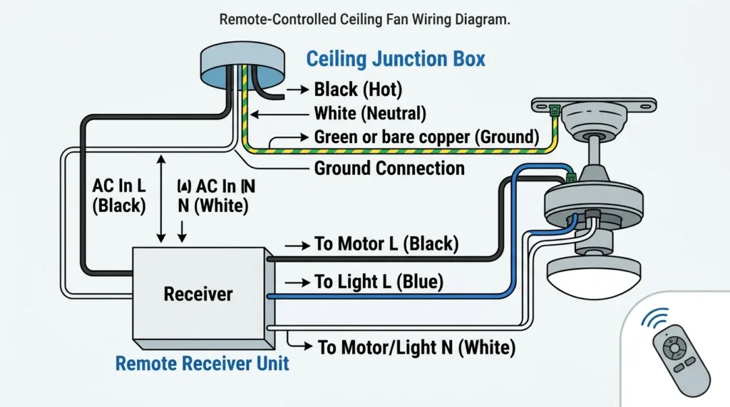
A remote-controlled ceiling fan wiring system uses a receiver unit installed inside the fan canopy and a handheld remote transmitter to control the fan. The live (phase) and neutral wires from the power supply are connected to the receiver, which then supplies power to the fan motor and light (if fitted). When a button on the remote is pressed, the transmitter sends a wireless signal to the receiver, allowing the user to turn the fan on or off, adjust the fan speed, and control the light without using a wall switch. This wiring system provides convenience, energy efficiency, and easy operation from anywhere within the remote’s range.
Modern fans use wireless remote systems.
Features
No manual regulator
Remote speed adjustment
Smart control
Applications
Smart homes
Modern apartments
Smart Ceiling Fan Wiring
Integrated with home automation systems.
Features
Wi-Fi connectivity
Mobile app control
Voice assistant operation
Applications
Smart buildings
Energy-efficient homes
Main Components
Understanding ceiling fan wiring components helps in installation and troubleshooting.
Ceiling Fan Motor
The motor rotates the fan blades using electrical energy.
Capacitor
The capacitor creates starting torque and improves motor performance.
Function
Helps motor start
Maintains smooth operation
Fan Regulator
Controls fan speed by adjusting voltage or current.
Switch
Turns the fan ON and OFF.
Wiring Conductors
Electrical wires carry current through the circuit.
Common Wires
Phase wire
Neutral wire
Ground wire
Mounting Box
Supports and protects wiring connections.
Fan Blades
Move air when rotated by the motor.
Advantages
Understanding ceiling fan wiring diagram advantages and disadvantages helps users install safer systems.
Advantages of Ceiling Fan Wiring Diagram
Simplifies installation process
Reduces wiring mistakes
Improves electrical safety
Helps troubleshooting
Supports proper maintenance
Saves installation time
Useful for students and technicians
Helps understand current flow
Reduces risk of short circuits
Improves repair efficiency
Disadvantages / Limitations
Although wiring diagrams are very useful, they also have some limitations.
Disadvantages of Ceiling Fan Wiring Diagram
Beginners may find diagrams confusing initially
Incorrect interpretation can cause wiring faults
Different fan brands use different wiring methods
Complex smart fans require advanced knowledge
Poor-quality diagrams may create confusion
Wiring work still requires electrical safety precautions
Ceiling Fan Wiring Diagram Applications
Ceiling fan wiring diagram applications are found in many electrical installations.
Home Applications
Bedroom ceiling fans
Kitchen ventilation fans
Living room cooling systems
Commercial Applications
Offices
Shopping centers
Restaurants
Schools
Industrial Applications
Ventilation systems
Workshop cooling
Warehouse airflow systems
Modern Technology Applications
Smart homes
IoT-based automation
Remote monitoring systems
Comparison Section
Difference Between Ceiling Fan Wiring and Exhaust Fan Wiring
| Feature | Ceiling Fan Wiring | Exhaust Fan Wiring |
| Main Purpose | Air circulation | Air removal |
| Speed Control | Usually available | Limited |
| Capacitor Use | Required | Sometimes required |
| Installation Position | Ceiling | Wall or window |
| Blade Design | Large blades | Compact blades |
| Air Direction | Room circulation | Outside ventilation |
| Common Use | Cooling rooms | Removing heat and odor |
Selection Guide
Choosing the right ceiling fan wiring system depends on application, safety, and user requirements.
Choose Basic Wiring When
Installing standard home fans
Budget is limited
Simple control is needed
Choose Regulator Wiring When
Adjustable speed is important
Better comfort is required
Choose Smart Wiring When
Home automation is used
Remote operation is preferred
Energy monitoring is needed
Tips for Beginners
Always Follow Wiring Diagram
Never connect wires randomly.
Turn OFF Main Power
Disconnect electrical supply before installation.
Use Proper Wire Size
Correct wire thickness improves safety.
Check Capacitor Rating
Wrong capacitor values can damage the motor.
Verify Connections Carefully
Loose connections may cause overheating.
Common Problems & Solutions
Why Is the Ceiling Fan Not Starting?
causes:
Power supply failure
Faulty capacitor
Loose wiring
Solution
Check voltage supply
Replace capacitor
Tighten connections
Why Is the Fan Running Slowly?
reasons:
Weak capacitor
Low voltage
Faulty regulator
Solution
Replace capacitor
Inspect voltage level
Repair regulator
Why Does the Fan Make Noise?
Noise may occur due to loose parts or bearing problems.
Solution
Tighten screws
Lubricate bearings
Balance blades properly
Why Does the Fan Overheat?
causes:
Overloaded motor
Poor ventilation
Damaged winding
Solution
Reduce operating load
Improve airflow
Repair motor winding
Why Does the Circuit Breaker Trip?
Short circuits or insulation faults can trip breakers.
Solution
Inspect wiring carefully
Replace damaged wires
Check grounding
Future Trends
Ceiling fan technology is improving with modern electrical innovations.
Smart Ceiling Fans
Smart fans now support:
Mobile app control
Voice commands
Automatic speed adjustment
Energy-Efficient Motors
Modern fans use BLDC motors for lower power consumption.
Benefits
Higher efficiency
Silent operation
Longer lifespan
IoT Integration
Future ceiling fans will connect with smart home systems automatically.
Sensor-Based Automation
Fans may automatically adjust speed based on:
Room temperature
Humidity
Human presence
Wireless Power Control
Advanced wireless systems reduce complex manual wiring.
Conclusion
Understanding the ceiling fan wiring diagram is essential for safe installation, maintenance, and troubleshooting of ceiling fan systems. A proper wiring diagram helps electrical students, engineers, technicians, and beginners understand how electrical current flows through switches, regulators, capacitors, and motor windings to operate the fan efficiently.
The ceiling fan wiring diagram working principle also explains how different components work together to provide smooth airflow and speed control. Different wiring systems are available for basic fans, smart fans, and remote-controlled models, depending on user needs and modern technology requirements.
As electrical systems continue to evolve, smart fan technology, energy-efficient motors, and automated control systems are becoming more common. Learning proper wiring methods and safety practices is an important step toward becoming skilled in electrical installation and maintenance work.