
Imagine walking into a classroom, office, or workshop and seeing bright white light spread evenly across the entire room. In many buildings, this lighting comes from tube lights, which are widely used because they provide efficient and uniform illumination. Although tube lights appear simple from the outside, their internal wiring system involves several important electrical components working together safely and efficiently.
Understanding tube light wiring explained is important for electrical students, engineers, technicians, and beginners. Proper wiring ensures smooth operation, reduces electrical faults, improves safety, and increases the lifespan of lighting systems. Incorrect wiring may cause flickering, overheating, short circuits, or complete lighting failure.
Learning the tube light wiring explained working principle also helps beginners understand how electricity flows through components such as ballast, starter, holders, and fluorescent tubes. This knowledge is useful during installation, troubleshooting, and maintenance work.
In this article, you will learn everything about tube light wiring explained, including its working principle, types, components, advantages and disadvantages, applications, comparison, troubleshooting methods, selection guide, and future lighting technologies in simple and easy English.
What Is Tube Light Wiring?
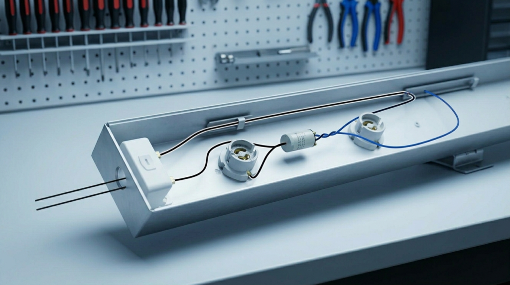
Tube light wiring is the method of connecting the electrical components of a fluorescent tube light so that the lamp can start, operate, and produce light safely. A traditional fluorescent tube light circuit commonly includes a power supply, ballast, starter, tube holders, and fluorescent tube.
The wiring provides a controlled path for electrical current through the circuit. The ballast limits and controls the current after the lamp starts, while the starter helps initiate the starting process in traditional fluorescent fixtures.
In simple terms, tube light wiring connects all the required components in the correct electrical arrangement so the fluorescent tube can start and continue producing light.
A typical traditional circuit can be represented as:
AC Supply → Switch → Ballast → Tube → Neutral
The starter is connected across the appropriate tube electrodes as part of the starting circuit.
Important: Modern fluorescent fixtures may use an electronic ballast and may not use a separate starter. LED tube lights can also use completely different wiring arrangements, so the wiring method must always match the specific lamp and fixture design.
Simple Explanation of Tube Light Wiring
A traditional fluorescent tube does not normally operate by simply connecting it directly to the AC supply. It requires a starting and current-control arrangement.
When the switch is turned ON, the ballast and starter work together to initiate the lamp. Once the fluorescent tube starts conducting and producing light, the ballast limits the current to keep the lamp operating within its designed range.
The wiring system therefore performs several important functions:
- Provides electrical power to the lamp
- Helps start the fluorescent tube
- Controls the operating current
- Provides a complete electrical circuit
- Allows stable operation of the lamp
- Helps protect the circuit from excessive current
Main Components Involved
Ballast
The ballast is used to limit the current flowing through the fluorescent tube. In traditional magnetic-ballast systems, it is also involved in generating the voltage needed during the starting process.
Starter
The starter is used in traditional fluorescent tube circuits to help preheat the electrodes and initiate the starting sequence. Once the tube starts, the starter normally stops conducting.
Fluorescent Tube
The fluorescent tube contains a low-pressure gas and a phosphor coating on the inside of the glass. When the lamp operates, an electrical discharge produces ultraviolet radiation, which causes the phosphor coating to emit visible light.
Tube Holders
Tube holders, also called lamp holders, mechanically support the tube and provide electrical connections to its electrodes.
Switch
The switch controls the supply to the tube light circuit. When the switch is turned ON, power is supplied to the starting and operating circuit.
Practical Example of Tube Light Wiring
A traditional fluorescent tube light installed in a home, office, classroom, or workshop may use a phase conductor, neutral conductor, ballast, starter, and two tube holders.
When the wall switch is turned ON, the supply reaches the tube-light circuit. The starter initially allows current to flow through the lamp electrodes, causing them to heat. The starter then opens its contacts, and the ballast produces a voltage pulse that helps establish the discharge inside the tube.
After the tube starts, the electrical discharge is maintained through the gas inside the lamp. The ballast then limits the current so the lamp can continue operating safely.
The complete process happens very quickly, which is why the user normally sees the tube flash or flicker briefly before it becomes fully illuminated.
Working Principle of Tube Light Wiring
The working principle of traditional fluorescent tube light wiring is based on gas discharge, electrode heating, and controlled current flow.
Unlike an ordinary resistive lamp, a fluorescent tube requires a starting process to establish an electrical discharge through the low-pressure gas inside the tube.
The ballast and starter perform important roles during this process.
Step-by-Step Working Principle
1. Power Supply Is Connected
When the wall switch is turned ON, AC electrical power is supplied to the tube-light circuit.
The current enters the circuit through the phase conductor and passes through the appropriate components.
2. Current Passes Through the Starting Circuit
In a traditional magnetic-ballast circuit, the current initially flows through the ballast, one tube electrode, the starter, and the other tube electrode.
The starter is initially closed, allowing current to flow through the lamp electrodes.
3. Tube Electrodes Are Heated
Current flowing through the electrodes heats them.
Heating the electrodes helps prepare the fluorescent tube for the discharge that will produce light.
4. Starter Opens
After the electrodes have been heated, the starter contacts open.
This sudden interruption of current causes the magnetic ballast to generate a high-voltage pulse.
5. Electrical Discharge Starts
The voltage pulse helps establish an electrical discharge through the gas inside the fluorescent tube.
Once the discharge is established, the lamp begins producing ultraviolet radiation.
6. Phosphor Produces Visible Light
The inside surface of a fluorescent tube is coated with phosphor material.
The ultraviolet radiation produced by the gas discharge excites the phosphor coating, causing it to emit visible light.
This is how the electrical energy is converted into useful illumination.
7. Ballast Controls the Current
After the tube has started, the ballast limits the current flowing through the lamp.
This is important because a fluorescent discharge lamp can draw increasing current if it is not properly controlled.
The ballast therefore helps keep the lamp operating within its intended electrical range.
8. Continuous Lighting Is Maintained
Once the discharge is established and the current is controlled, the tube continues producing light as long as the circuit remains energized.
The starter remains open during normal operation in a traditional starter-based circuit.
How the Starter and Ballast Work Together
The starter and ballast have different but related functions.
The starter helps prepare the lamp for starting by controlling the electrode-heating sequence.
The ballast helps provide the starting voltage and then limits the operating current.
Their basic sequence can be summarized as:
Power ON → Starter Closes → Electrodes Heat → Starter Opens → Ballast Produces Starting Voltage Pulse → Gas Discharge Begins → Tube Produces Light → Ballast Limits Current
This sequence explains why a traditional fluorescent tube may briefly flicker before becoming fully illuminated.
Why a Ballast Is Necessary
A fluorescent tube requires current limitation during normal operation. The ballast performs this important function.
Without appropriate current control, the discharge inside the lamp could become unstable and excessive current could flow.
Traditional fixtures commonly use a magnetic ballast, while many newer fluorescent fixtures use an electronic ballast.
Electronic ballasts can operate at higher frequencies and may provide faster starting, reduced flicker, and improved electrical performance compared with traditional magnetic-ballast systems.
Traditional vs Electronic Tube Light Wiring
Traditional Magnetic Ballast System
A traditional fluorescent fixture generally uses:
- Magnetic ballast
- Separate starter
- Fluorescent tube
- Tube holders
- Switch
- AC supply
The starter and ballast work together during the starting process.
Electronic Ballast System
Electronic ballast fixtures use electronic circuitry to control the lamp.
They may not require a separate starter because the electronic ballast performs the starting function internally.
Advantages can include:
- Faster starting
- Reduced visible flicker
- Improved control of lamp current
- Potentially better efficiency
- More compact fixture design
The exact wiring depends on the fixture and ballast manufacturer.
Basic Tube Light Wiring Flow
For a traditional fluorescent tube circuit, the operating sequence can be understood as:
AC Supply → Switch → Ballast → Tube Electrodes → Starter/Starting Circuit → Tube Discharge → Controlled Current → Light Output
The exact physical connection depends on the specific fixture design, so electricians should follow the manufacturer’s wiring diagram rather than relying only on a generic diagram.
Important Safety Considerations
Fluorescent tube-light circuits operate at hazardous electrical voltages. Power should be isolated before wiring, repairing, or replacing components.
A suitable circuit protection device should be provided, and all connections should be properly insulated and secured.
The ballast, starter, tube, and other components must be compatible with each other. Incorrect wiring can cause flickering, overheating, failure to start, or electrical hazards.
Older fluorescent fixtures may also contain components that require appropriate handling and disposal. Local requirements should be followed when replacing or disposing of fluorescent lamps and associated electrical components.
Key Points to Remember
Electrical power should be isolated before installation or maintenance.
Tube light wiring connects the supply and lamp components in a controlled circuit.
Traditional fluorescent systems commonly use a ballast and starter.
The starter helps with electrode heating and the starting sequence.
The ballast helps generate the starting voltage and limits operating current.
The fluorescent tube produces light through an electrical discharge and phosphor coating.
Electronic-ballast fixtures may not require a separate starter.
LED tube lights use different wiring arrangements depending on their design.
Always follow the fixture manufacturer’s wiring diagram.
Step-by-Step Tube Light Wiring Working Process
Understanding the tube light wiring working process makes it easier to understand how a traditional fluorescent tube light starts and continues producing light. In a conventional fluorescent tube light circuit, the phase and neutral supply, ballast, starter, tube electrodes, and fluorescent tube work together in a specific sequence.
The following steps explain the fluorescent tube light wiring and working principle in simple terms.
Power Supply Enters the Tube Light Circuit
When the wall switch is turned ON, AC electrical power enters the tube light circuit through the phase and neutral conductors.
The phase wire supplies electrical energy to the circuit, while the neutral wire provides the return path. The electrical supply first passes through the switching and ballast arrangement before the starting process begins.
The supply voltage must be suitable for the ballast and fluorescent tube being used. Incorrect voltage or incompatible components can cause starting problems, flickering, overheating, or premature lamp failure.
Ballast Controls Current and Supports Starting
The ballast is one of the most important components in traditional fluorescent tube light wiring.
During starting, a magnetic ballast helps produce the voltage pulse required to initiate the electrical discharge inside the tube. After the lamp starts, the ballast limits the current flowing through the fluorescent tube.
This current-limiting function is important because a fluorescent discharge lamp cannot normally be connected directly across the supply without an appropriate current-control device.
In traditional systems, the ballast therefore performs two important functions:
- Helps generate the starting voltage
- Limits the operating current
Modern fluorescent fixtures may use an electronic ballast, which performs the starting and current-control functions electronically.
Starter Closes and Heats the Tube Electrodes
In a traditional starter-based fluorescent circuit, the starter initially closes its contacts when power is applied.
This allows current to flow through the tube’s electrodes, causing them to heat. Heated electrodes help establish the conditions required for the fluorescent discharge to start.
The starter is therefore part of the starting sequence rather than a component that continuously controls the lamp during normal operation.
After a short period, the starter contacts open.
Starter Opens and Creates a Voltage Pulse
When the starter opens its contacts, the current through the magnetic ballast is suddenly interrupted.
Because the ballast is an inductive component, this rapid interruption produces a high-voltage pulse. The pulse is applied across the fluorescent tube and helps initiate the electrical discharge through the gas inside the lamp.
This is the key transition between the electrode-heating stage and the actual lamp-starting stage.
If the starter or ballast is faulty, the tube may repeatedly flash, flicker, or fail to start.
Gas Ionization Occurs Inside the Fluorescent Tube
Once the required starting voltage is established, an electrical discharge begins through the low-pressure gas inside the fluorescent tube.
The tube contains a small amount of mercury and a starting gas. During operation, the discharge causes mercury atoms to emit mainly ultraviolet radiation.
This process is often described as gas ionization and electrical discharge.
The ultraviolet radiation itself is not the visible light that normally illuminates the room. Instead, it interacts with the phosphor coating inside the tube.
Phosphor Coating Produces Visible Light
The inside of a fluorescent tube is coated with a layer of phosphor material.
When ultraviolet radiation produced by the mercury discharge reaches this phosphor coating, the phosphor converts much of that energy into visible light.
This is why the tube produces useful illumination even though the initial radiation generated inside the lamp is primarily ultraviolet.
The basic energy conversion can be represented as:
Electrical Energy → Gas Discharge → Ultraviolet Radiation → Phosphor → Visible Light
Ballast Maintains Controlled Lamp Operation
After the fluorescent tube has successfully started, the ballast continues to perform its current-limiting function.
It prevents the lamp current from increasing excessively and helps keep the discharge operating within the intended range.
In a magnetic-ballast system, the ballast may also introduce some electrical losses and can contribute to audible humming or visible flicker. Electronic ballasts are designed differently and can provide more advanced control.
Tube Continues Producing Light
Once the electrical discharge has been established and the current is properly controlled, the fluorescent tube continues producing visible light as long as the circuit remains energized.
The starter normally remains open during normal operation in a traditional starter-based circuit.
The lamp therefore changes from a starting condition into a stable operating condition.
Switching the Tube Light OFF
When the wall switch is turned OFF, the electrical supply to the tube light circuit is interrupted.
The electrical discharge inside the tube stops, and the fluorescent tube stops producing light.
When the circuit is switched ON again, the starting sequence repeats in a traditional ballast-and-starter system.
Simple Tube Light Wiring Working Flow
The complete working process of a traditional fluorescent tube light can be summarized as:
AC Supply → Switch → Ballast → Starter/Electrode Heating → Starter Opens → Starting Voltage Pulse → Gas Discharge → UV Radiation → Phosphor Coating → Visible Light
This sequence explains the basic tube light wiring and working principle used in traditional fluorescent fixtures.
Why a Tube Light May Flicker or Fail to Start
Understanding the working process also helps explain common tube light problems.
A fluorescent tube may flicker or repeatedly attempt to start because of:
- Weak or faulty starter
- Aging fluorescent tube
- Faulty ballast
- Loose electrical connection
- Incorrect component compatibility
- Low or unstable supply voltage
- Damaged tube electrodes
A qualified electrician should inspect the circuit before replacing components or modifying the wiring.
Traditional and Electronic Tube Light Starting
Not every fluorescent tube light uses the traditional starter-and-magnetic-ballast arrangement.
Traditional fixtures commonly use:
Magnetic Ballast + Separate Starter + Fluorescent Tube
Many newer fluorescent fixtures use:
Electronic Ballast + Fluorescent Tube
An electronic ballast can control the starting and operating process electronically and does not normally require a separate glow starter.
Therefore, the actual fluorescent tube light wiring diagram should always be checked against the fixture and ballast manufacturer’s instructions.
Key Points of Tube Light Working Principle
Electronic-ballast fluorescent fixtures may use a different starting method.
AC power supplies the tube light circuit.
The ballast controls the lamp current.
A traditional starter helps heat the tube electrodes.
The starter opens after the electrodes are heated.
The magnetic ballast produces a starting voltage pulse.
An electrical discharge is established inside the fluorescent tube.
Mercury vapor produces ultraviolet radiation during operation.
The phosphor coating converts ultraviolet radiation into visible light.
The ballast continues limiting the operating current.
Phosphor Coating Produces Visible Light
Phosphor coating is a thin layer of special chemical material applied to the inside of fluorescent lamps and other lighting devices. When ultraviolet (UV) rays strike the phosphor coating, it absorbs the invisible energy and converts it into visible light. This process, known as fluorescence, makes the lamp glow brightly and efficiently. Different types of phosphor coatings produce different colors of light, making them useful in various lighting and display applications.
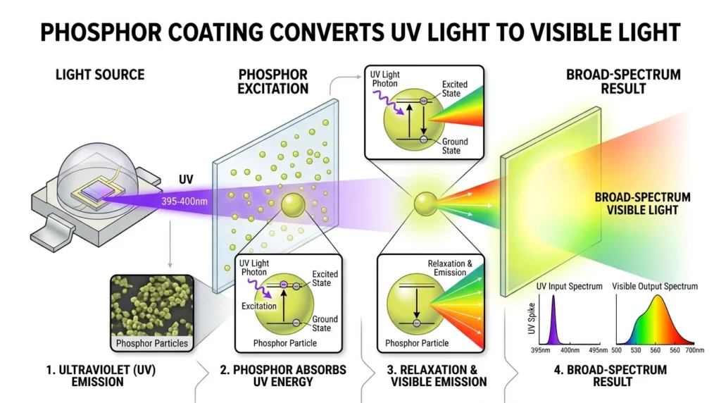
The phosphor coating inside the tube converts ultraviolet light into visible white light.
Easy Analogy
Think of a tube light like a water pump system:
Ballast acts like a pressure controller
Starter acts like an ignition switch
The tube acts like a glowing pathway for electricity
Current Flow Sequence
Power Supply → Switch → Ballast → Starter → Tube Light → Neutral
Types / Classification
Different tube light wiring systems are used depending on lighting technology and application.
Traditional Tube Light Wiring Method
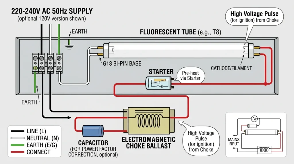
A traditional fluorescent tube light wiring circuit uses a fluorescent tube, magnetic choke or ballast, starter, tube holders, switch, and AC power supply. This type of wiring was widely used in homes, schools, offices, workshops, and commercial buildings before electronic ballasts and LED lighting became more common.
When the switch is turned ON, current initially flows through the starter and the filaments at both ends of the fluorescent tube. The filaments heat up and prepare the gas inside the tube for discharge. After a short time, the starter opens the circuit. This sudden interruption of current causes the magnetic choke to generate a high-voltage pulse.
The high-voltage pulse helps ionize the low-pressure gas inside the tube and establishes an electrical discharge. The mercury vapor produces ultraviolet (UV) radiation, which strikes the phosphor coating on the inside of the tube. The phosphor converts the UV radiation into visible light.
Once the tube starts operating, the choke or magnetic ballast limits and regulates the current to prevent excessive current from damaging the lamp.
This is the traditional fluorescent tube light wiring method, commonly found in older lighting installations.
Features of Traditional Tube Light Wiring
- Uses a magnetic choke or ballast for current regulation.
- Requires a starter for the traditional starting process.
- Uses fluorescent tube holders to connect the lamp electrodes.
- Uses heated electrodes to help initiate the discharge.
- Produces visible light through gas discharge and phosphor conversion.
- Commonly found in older electrical installations.
- The magnetic ballast may produce a slight humming sound during operation.
- Starting performance can be affected by low temperature or a weak starter.
- Generally has more starting components than modern LED lighting systems.
Applications of Traditional Fluorescent Tube Light Wiring
Traditional fluorescent tube lights were widely used for general-purpose indoor lighting, particularly where long operating hours and broad-area illumination were required.
Common applications include:
- Schools and educational buildings for classrooms and corridors.
- Offices for general workspace illumination.
- Workshops for lighting work areas and maintenance spaces.
- Shops and commercial buildings for indoor lighting.
- Warehouses where long fluorescent tubes were used for wide-area illumination.
- Factories for general production and working areas.
- Hospitals and institutional buildings in older lighting systems.
- Residential buildings where conventional fluorescent fixtures were installed.
Traditional Tube Light Wiring vs Modern Lighting
Although traditional fluorescent tube light wiring is still found in many older installations, it has largely been replaced by electronic-ballast fluorescent fixtures and LED tube lights. Modern systems can offer simpler starting, better energy efficiency, reduced maintenance, and improved control depending on the fixture design.
When replacing a traditional fluorescent tube, the replacement lamp and wiring method must be checked carefully. LED tubes do not all use the same wiring arrangement, so the manufacturer’s wiring instructions should always be followed.
Electronic Ballast Tube Light Wiring
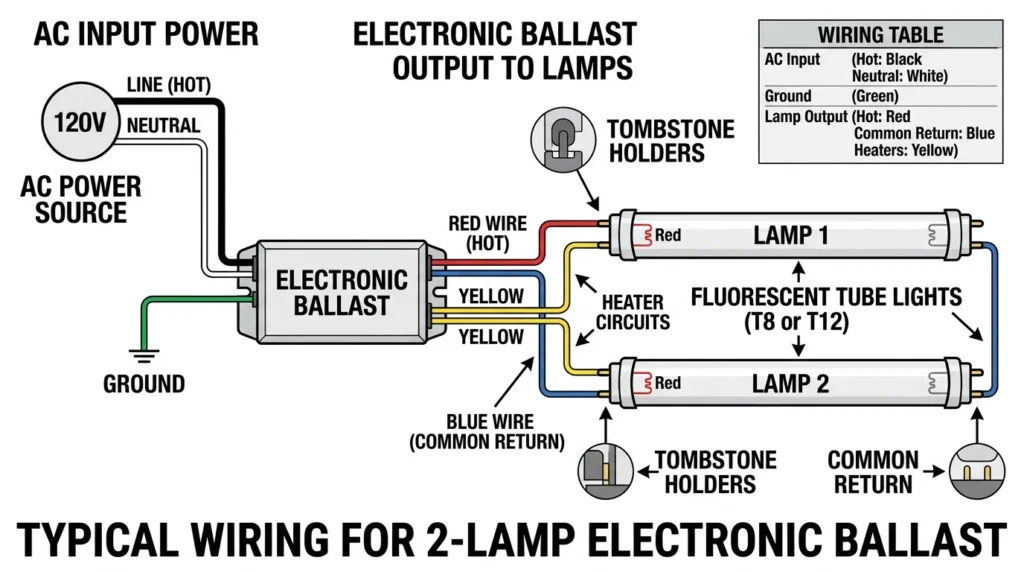
An electronic ballast tube light wiring system uses an electronic ballast instead of the conventional magnetic choke and starter. The electronic ballast controls the electrical supply to the fluorescent tube and operates it at a much higher frequency than a traditional magnetic ballast.
When the power is switched ON, the electronic ballast quickly provides the voltage and starting conditions required to initiate the fluorescent tube. Unlike a traditional fluorescent tube light circuit, a separate starter is normally not required. The electronic ballast performs the starting and current-control functions electronically.
After the tube starts, the electronic ballast regulates the current flowing through the lamp and maintains stable operation. Because the lamp operates at high frequency, visible flickering and the typical humming noise associated with magnetic ballasts can be greatly reduced.
Electronic ballast systems can also provide better energy efficiency and lower heat generation than older magnetic-ballast systems, depending on the ballast design and lamp. They were widely used in modern fluorescent lighting fixtures before LED lighting became the dominant replacement technology.
Features of Electronic Ballast Tube Light Wiring
- Uses an electronic ballast instead of a magnetic choke.
- Normally does not require a separate conventional starter.
- Provides faster and smoother lamp starting.
- Operates the fluorescent tube at high frequency.
- Reduces visible flickering compared with traditional magnetic-ballast systems.
- Produces less audible humming noise.
- Can improve system efficiency and reduce ballast losses.
- Generally produces less wasted heat than older magnetic ballasts.
- Provides controlled current to the fluorescent tube.
- Can support more stable fluorescent lamp operation.
Applications of Electronic Ballast Tube Light Wiring
Electronic ballast fluorescent lighting was commonly used in modern indoor lighting installations where efficient and comfortable illumination was required.
Common applications include:
- Commercial buildings for general-purpose lighting.
- Modern offices to provide stable and comfortable workspace illumination.
- Schools and colleges for classrooms, laboratories, and corridors.
- Hospitals and healthcare buildings where reduced flicker and reliable lighting were important.
- Retail stores for general indoor illumination.
- Factories and workshops for work-area lighting.
- Warehouses for large indoor spaces requiring long operating hours.
- Institutional buildings with extensive fluorescent lighting systems.
Electronic Ballast vs Magnetic Ballast
The main difference is that an electronic ballast uses electronic components to start and regulate the fluorescent lamp, while a magnetic ballast uses an electromagnetic choke and traditionally works with a separate starter.
Electronic ballast systems generally provide faster starting, less flicker, lower audible noise, and improved efficiency compared with conventional magnetic-ballast systems. However, the actual performance depends on the ballast, lamp type, fixture design, and operating conditions.
When replacing or rewiring an electronic-ballast fluorescent fixture, always follow the manufacturer’s wiring diagram. Electronic-ballast fixtures are not wired in exactly the same way as traditional choke-and-starter tube light circuits.
LED Tube Light Wiring
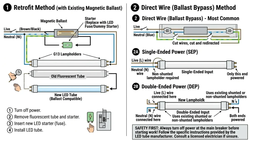
LED tube light wiring is simpler and more energy-efficient than traditional fluorescent tube light wiring because LED tubes do not use a conventional starter and magnetic choke. Depending on the design, an LED tube may connect directly to the AC supply through an internal LED driver, or it may use an external driver or ballast-compatible arrangement.
When the switch is turned ON, electrical power reaches the LED tube’s driver or internal control circuit. The driver converts and regulates the incoming electrical power to provide the appropriate voltage and current required by the LEDs. The LED chips then convert electrical energy into visible light.
Unlike traditional fluorescent tubes, LED tube lights do not require gas discharge, mercury vapor, or a phosphor coating to generate light. They use light-emitting diodes (LEDs), which produce light when electric current passes through semiconductor materials.
Many LED tube lights provide near-instant illumination and can offer very low flicker when properly designed and compatible with the supply. They generally consume less electricity, produce less waste heat, have a longer rated life, and require less maintenance than traditional fluorescent lighting.
Types of LED Tube Light Wiring
LED tube lights are available with different wiring arrangements. The correct method depends on the specific tube and fixture.
Direct-Wire LED Tube
A direct-wire LED tube is connected directly to the AC supply according to the manufacturer’s wiring diagram. These tubes typically have an internal driver that controls the current supplied to the LEDs.
Ballast-Compatible LED Tube
Some LED tubes are designed to operate with certain existing fluorescent ballasts. In this arrangement, the ballast remains part of the circuit, but compatibility must be confirmed before installation.
External Driver LED Tube
Some LED lighting systems use a separate external LED driver. The driver regulates the electrical supply before it reaches the LED tube or LED module.
Important: These wiring types are not interchangeable. Always identify the LED tube type and follow the manufacturer’s connection diagram before rewiring an existing fluorescent fixture.
Features of LED Tube Light Wiring
- No conventional starter required for standard LED tube designs.
- Uses an internal or external LED driver depending on the design.
- Provides fast or near-instant startup.
- Generally has lower power consumption than traditional fluorescent lighting.
- Can provide low-flicker operation when properly designed.
- Produces less wasted heat than many conventional lighting systems.
- Has a long rated operating life.
- Requires relatively little maintenance.
- Does not use mercury vapor like fluorescent tubes.
- Available in different lengths, wattages, color temperatures, and wiring configurations.
Applications of LED Tube Light Wiring
LED tube lights are widely used for energy-efficient general lighting in residential, commercial, industrial, and institutional environments.
Common applications include:
- Homes for kitchens, garages, corridors, and utility areas.
- Offices for workspaces, meeting rooms, and general lighting.
- Industries and factories for production and work areas.
- Warehouses for large indoor spaces.
- Schools and colleges for classrooms, laboratories, and corridors.
- Retail stores for general-purpose illumination.
- Hospitals and healthcare facilities where suitable LED lighting is required.
- Smart buildings as part of modern energy-efficient lighting systems.
- Workshops and maintenance areas where reliable and low-maintenance lighting is useful.
LED Tube Light Wiring Safety
Before replacing a fluorescent tube with an LED tube, check whether the existing fixture uses a magnetic ballast, electronic ballast, or another wiring arrangement. A direct-wire LED tube may require the ballast to be removed or bypassed, while a ballast-compatible model may have different requirements.
Never assume that all LED tubes use the same wiring method. Incorrect wiring can damage the tube, create a short circuit, or cause an electrical shock or fire hazard. Always switch OFF and isolate the power supply before working on the fixture, and follow the manufacturer’s wiring instructions and applicable electrical codes.
Key Point
The main advantage of LED tube light wiring is its simpler electronic design and lower energy use compared with traditional fluorescent lighting. However, the exact connection method depends on the LED tube design, so the manufacturer’s wiring diagram should always be used.
Single-End LED Tube Wiring
Single-end LED tube wiring is a wiring method in which the electrical power supply is connected to one end of the LED tube only. The Line (L) and Neutral (N) terminals are located on the designated input end, while the opposite end does not receive the main power supply.
This design simplifies the wiring arrangement and can make LED tube installation easier when the tube is specifically designed for single-end power input. However, the exact terminal arrangement can vary between LED tube models, so the manufacturer’s wiring instructions should always be followed.
Benefits of Single-End LED Tube Wiring
- Easy installation because power connections are made at one end.
- Simpler wiring compared with some double-end LED tube designs.
- Easy maintenance because the supply terminals are clearly identified.
- Reduced wiring complexity inside the lighting fixture.
- Reliable operation when the tube is correctly connected.
- Can be suitable for direct-wire LED tube retrofits when approved by the manufacturer.
Safety Considerations
Always confirm that the LED tube is designed for single-end power input before making the connection. Do not assume that every LED tube uses the same wiring arrangement.
Turn OFF and isolate the electrical supply before installation or rewiring. Connect Line and Neutral only to the terminals specified by the manufacturer and follow applicable electrical codes.
Double-End LED Tube Wiring
Double-end LED tube wiring is a wiring method in which the electrical supply is connected across both ends of the LED tube. Typically, one end is connected to Line (L) and the other end to Neutral (N), according to the manufacturer’s specified wiring arrangement.
When the power is switched ON, the electrical supply reaches the internal LED driver or circuit through the tube’s input terminals. The driver regulates the electrical current supplied to the LED chips, allowing the tube to produce light efficiently.
Double-end LED tubes are commonly used in commercial lighting and retrofit applications because their wiring arrangement can work well with many existing fixture configurations. However, the exact connection method varies between products, so the manufacturer’s wiring diagram must always be checked before installation.
Benefits of Double-End LED Tube Wiring
- Common in commercial installations for offices, stores, warehouses, and other large buildings.
- Simple replacement option for compatible fluorescent fixtures.
- Can provide a straightforward Line-to-Neutral connection.
- Easy to understand when the input terminals are clearly marked.
- Suitable for many direct-wire LED tube applications.
- Eliminates the need for a conventional fluorescent starter.
Safety Considerations
Not all LED tubes use the same double-end wiring arrangement. Some products may have specific Line and Neutral terminals, while others may use different configurations.
Before installation, check the markings on the LED tube and follow the manufacturer’s wiring diagram. If an existing fluorescent fixture contains a ballast, determine whether the LED tube is ballast-compatible or requires ballast bypass before making any wiring changes.
Always isolate the power supply before working on the fixture and ensure the installation complies with applicable electrical codes.
Single-End vs Double-End LED Tube Wiring
The main difference is the location of the electrical input. Single-end LED tubes receive power from one end, while double-end LED tubes receive power across both ends according to their specified wiring design. The correct method depends on the LED tube and fixture being installed.
Main Components
Understanding tube light components helps in proper installation and troubleshooting.
Fluorescent Tube
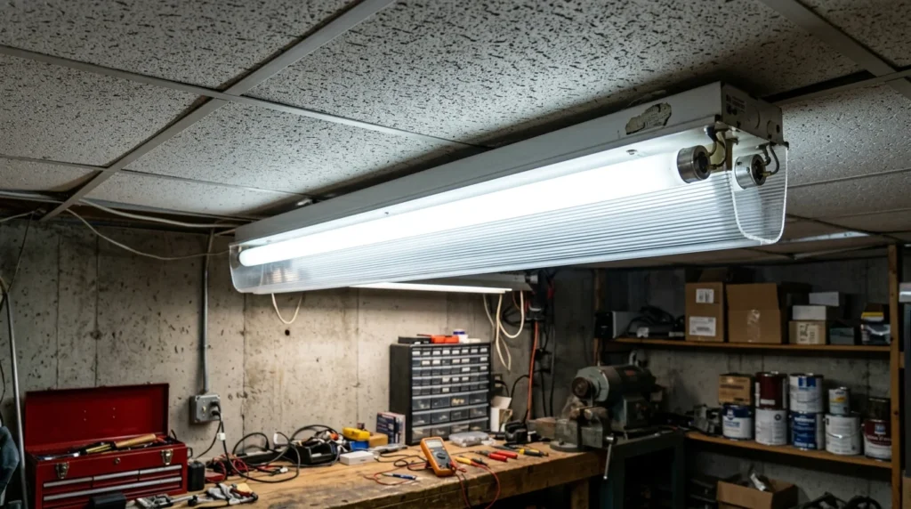
A fluorescent tube is an energy-efficient lighting device commonly used in homes, offices, schools, and industries. It is a glass tube filled with low-pressure mercury vapor and an inert gas, with a phosphor coating on the inside surface. When electric current passes through the tube, the mercury vapor produces ultraviolet (UV) rays. The phosphor coating absorbs these UV rays and converts them into visible light through a process called fluorescence. Fluorescent tubes provide bright illumination, consume less electricity than incandescent bulbs, and have a longer operating life.
The main lighting component containing gas and phosphor coating.
Main Components of Tube Light Wiring
A tube light wiring system contains several electrical and mechanical components that work together to start, operate, and control the lamp. The exact components depend on whether the fixture uses a traditional magnetic ballast, electronic ballast, or LED tube technology.
Ballast
The ballast controls the current flowing through a fluorescent tube and helps provide the electrical conditions required for starting.
Traditional fluorescent fixtures commonly use either a magnetic or electronic ballast.
Magnetic Ballast
A magnetic ballast uses an electromagnetic choke to limit lamp current. In traditional circuits, it works together with a starter to initiate the fluorescent tube.
Electronic Ballast
An electronic ballast uses electronic circuitry to start and regulate the fluorescent tube. It normally does not require a separate conventional starter and operates the lamp at a higher frequency.
Starter
A starter is used in traditional fluorescent tube light wiring. It initially allows current to flow through the tube electrodes, helping heat them before the starter opens the circuit and assists the ballast in producing the starting voltage.
Electronic-ballast fluorescent fixtures normally do not use a separate starter.
Tube Holders
Tube holders, also called lamp holders, mechanically support the fluorescent tube and provide electrical connections to its electrodes.
They must be correctly positioned and securely connected to ensure reliable operation.
Wiring Conductors
Wiring conductors carry electrical power between the supply, switch, ballast or driver, and lamp.
Common conductors include:
- Phase or Line wire: Carries the supply voltage to the circuit.
- Neutral wire: Provides the return path for the electrical circuit.
- Ground or Protective Earth wire: Provides a safety path for fault current where required by the installation.
The actual conductor arrangement depends on the fixture design and local electrical requirements.
Switch
The switch controls the power supplied to the tube light. When the switch is turned ON, the lighting circuit receives power. When it is turned OFF, the lamp is disconnected from the normal supply path.
Capacitor
A capacitor may be used in some fluorescent lighting circuits, particularly with magnetic ballasts, to improve the power factor of the installation.
A capacitor is not required in every tube light circuit, and its value and connection must match the specific fixture and electrical system.
Advantages of Tube Light Wiring
Understanding the advantages and disadvantages of tube light wiring helps users select an appropriate lighting system for homes, offices, workshops, and commercial spaces.
Advantages of Tube Light Wiring
- Provides uniform lighting over relatively large areas.
- Generally uses less electricity than older incandescent bulbs for comparable illumination.
- Suitable for large areas such as offices, classrooms, workshops, and warehouses.
- Can provide a lower operating cost when compared with older, less-efficient lighting technologies.
- Fluorescent tubes can have a relatively long rated life when operated with suitable components.
- Provides good brightness distribution across working areas.
- Available in different lengths, wattages, and color temperatures.
- Easy maintenance when replacement tubes and compatible components are readily available.
- Suitable for many commercial and institutional applications.
- Produces less radiant heat than incandescent lighting for the same general lighting task.
- Modern electronic-ballast systems can reduce flicker and audible noise compared with traditional magnetic-ballast fixtures.
Important Advantage of LED Tube Lights
Modern LED tube lights can provide additional benefits such as lower energy consumption, long rated life, instant startup, and reduced maintenance compared with conventional fluorescent tubes.
However, LED performance depends on the tube design, driver quality, installation method, and operating conditions.
Disadvantages and Limitations of Tube Light Wiring
Although fluorescent tube lights have been widely used, conventional tube light systems also have several limitations.
Disadvantages of Tube Light Wiring
- Traditional fluorescent systems may flicker, particularly when the lamp or ballast is aging or faulty.
- Magnetic ballasts can produce humming noise during operation.
- Starters can fail over time, causing delayed starting or repeated flashing.
- Fluorescent tubes contain mercury, so they require appropriate handling and disposal when broken or discarded.
- Conventional fluorescent wiring is more complex than a simple lamp circuit because it may require a ballast, starter, and multiple connections.
- Glass fluorescent tubes can break easily if handled improperly.
- Low temperatures can affect starting and light output in some fluorescent lamps.
- Magnetic ballasts can consume additional power as ballast losses.
- Faulty ballasts may overheat or cause abnormal lamp operation.
- Older fluorescent systems generally require more maintenance than modern LED lighting.
- Replacing a fluorescent tube with an LED tube may require checking or modifying the existing wiring.
Key Point
The advantages and limitations of a tube light depend heavily on the technology being used. Traditional fluorescent tube lights use components such as a ballast and, in many designs, a starter, while modern LED tube lights use LED drivers and different wiring arrangements.
Therefore, always identify the lamp type before troubleshooting, replacing components, or modifying the wiring. Follow the manufacturer’s wiring diagram and applicable electrical safety requirements.
Tube Light Wiring Explained Applications
Tube light wiring explained applications are common in many sectors.
Home Applications
Kitchens
Study rooms
Garages
Commercial Applications
Offices
Shopping malls
Schools
Hospitals
Industrial Applications
Factories
Warehouses
Workshops
Modern Technology Applications
Smart lighting systems
LED retrofitting
Energy-saving installations
Difference Between Fluorescent Tube Light and LED Tube Light
Fluorescent and LED tube lights are both used for general lighting, but they work using different technologies. Fluorescent tubes produce light through a gas-discharge process, while LED tubes use semiconductor devices to produce visible light.
| Feature | Fluorescent Tube Light | LED Tube Light |
|---|---|---|
| Technology | Gas discharge | Semiconductor |
| Starter Required | Usually required in traditional systems | Normally no conventional starter |
| Ballast | Magnetic or electronic ballast required | Depends on design; may be direct-wire, driver-based, or ballast-compatible |
| Energy Efficiency | Moderate | Generally higher |
| Rated Lifespan | Generally shorter than LED | Generally longer |
| Heat Generation | Moderate | Generally lower wasted heat |
| Mercury | Contains mercury | Does not use mercury vapor |
| Startup | May have a short starting delay | Usually instant or near-instant |
| Flickering | More likely in older systems | Generally lower when properly designed |
| Maintenance | More components may require replacement | Generally lower maintenance |
| Power Consumption | Generally higher | Generally lower |
| Replacement | Requires compatible fluorescent components | Requires correct LED tube and wiring arrangement |
Which Tube Light Is More Energy Efficient?
LED tube lights are generally more energy-efficient than conventional fluorescent tubes because LEDs convert electrical energy into light without the same discharge and ballast losses associated with fluorescent systems.
The actual energy savings depend on the lamp wattage, ballast losses, operating hours, light output, and fixture design.
Tube Light Wiring Selection Guide
Choosing the right tube light wiring system depends on the type of lamp, existing fixture, required efficiency, installation conditions, maintenance requirements, and budget.
Before replacing or installing a tube light, identify whether the system uses a traditional magnetic ballast, electronic ballast, or LED driver.
Choose Conventional Fluorescent Tube Lights When
- An existing fluorescent system is already installed and maintained properly.
- Compatible replacement tubes and components are readily available.
- The existing fixture is still suitable for the required lighting application.
- The initial replacement budget is limited and a complete LED conversion is not currently planned.
For older installations, inspect the condition of the ballast, starter, holders, wiring, and fixture before continued use.
Choose Electronic Ballast Fluorescent Systems When
- Reduced flickering is important.
- Lower audible noise is desired compared with magnetic-ballast systems.
- Better fluorescent system efficiency is required.
- A modern fluorescent fixture is being maintained rather than converted to LED.
Electronic ballast systems generally provide smoother starting and higher-frequency operation.
Choose LED Tube Lights When
- Energy saving is a priority.
- Long rated operating life is required.
- Low maintenance is preferred.
- Instant or near-instant startup is desired.
- A modern lighting system is being installed or upgraded.
- Smart lighting controls or automation are required.
Always select an LED tube that matches the intended wiring method, such as single-end, double-end, direct-wire, or ballast-compatible operation.
Tube Light Wiring Tips for Beginners
Always Turn OFF the Power
Switch OFF and isolate the electrical supply before performing any wiring, replacement, or maintenance work. Verify that the circuit is de-energized before touching conductors.
Follow the Wiring Diagram Carefully
Different fluorescent and LED tube lights can have different connection requirements. Incorrect wiring can damage the lamp or create an electrical shock, short-circuit, or fire hazard.
Always follow the wiring diagram supplied by the manufacturer.
Use the Correct Wire Size
Select conductors that are suitable for the circuit voltage, current, installation method, temperature, and applicable electrical code. Correct conductor sizing improves safety and reliability.
Check Component Compatibility
Make sure the tube, ballast, starter, driver, lamp holders, and other components are compatible with each other.
This is especially important when replacing a fluorescent tube with an LED tube.
Ensure Proper Grounding
Where required, properly connect the protective earth or grounding conductor to the metal fixture and electrical system. Proper grounding helps reduce the risk of electric shock during a fault.
Common Tube Light Problems and Solutions
Tube light problems can be caused by the lamp, starter, ballast, wiring, power supply, or electrical connections. Proper troubleshooting should begin with basic checks before replacing components.
Why Is the Tube Light Flickering?
Common causes include:
- Faulty or aging starter
- Weak or defective fluorescent tube
- Faulty magnetic ballast
- Loose electrical connection
- Poor lamp-holder contact
- Incompatible LED tube or driver
Solution
- Replace the starter if the fixture uses one.
- Test or replace the fluorescent tube if it is defective.
- Inspect the ballast for signs of failure.
- Check lamp-holder and wiring connections.
- For LED tubes, verify the correct wiring arrangement and driver compatibility.
Why Does the Tube Light Not Start?
Possible causes include:
- No electrical power
- Failed fluorescent tube
- Faulty starter
- Defective ballast
- Loose connection
- Failed LED driver in an LED tube
Solution
- Check the power supply and switch.
- Inspect the tube and holders.
- Replace a faulty starter where applicable.
- Test the ballast or driver.
- Inspect wiring connections for damage or looseness.
Why Does the Ballast Overheat?
A ballast may overheat because of internal failure, incorrect lamp compatibility, poor ventilation, excessive operating temperature, or other circuit problems.
Solution
- Switch OFF the power and inspect the fixture.
- Check whether the ballast is rated for the lamp.
- Ensure adequate ventilation around the fixture.
- Replace a defective ballast with a compatible rated unit.
- Do not continue operating a ballast that shows signs of severe overheating, burning, or damage.
Why Is There a Humming Noise?
A noticeable humming sound is commonly associated with magnetic ballast vibration.
Solution
- Check and tighten the ballast mounting.
- Inspect the ballast for signs of aging or damage.
- Replace a defective ballast.
- Consider an electronic ballast or LED conversion where appropriate.
Why Does the Circuit Breaker Trip?
A circuit breaker may trip because of a short circuit, damaged insulation, incorrect wiring, excessive load, or a defective component.
Solution
- Switch OFF the circuit.
- Inspect the wiring and connections.
- Check for damaged insulation or signs of burning.
- Test the fixture and components.
- Have a qualified electrician investigate repeated breaker trips rather than repeatedly resetting the breaker.
Future Trends in Tube Light Technology
Lighting technology continues to move toward higher efficiency, longer operating life, digital controls, and better energy management. LED technology is already replacing many conventional fluorescent installations.
LED Tube Light Expansion
LED tube lights are increasingly replacing fluorescent systems because they can provide lower energy consumption, long rated life, instant startup, and reduced maintenance.
Key Benefits
- Lower power consumption
- Long rated operating life
- Reduced maintenance
- No mercury vapor
- Fast startup
- Compatibility with modern lighting controls in suitable products
Smart Lighting Systems
Modern LED lighting systems can be integrated with smart controls for improved energy management.
Common features include:
- Remote control
- Dimming
- Motion sensors
- Occupancy sensors
- Automatic scheduling
- Building automation
- Energy monitoring
IoT-Based Lighting
IoT-based lighting systems can connect lighting fixtures to networks and control platforms. This allows lighting to be monitored and controlled automatically according to occupancy, time, daylight levels, and building requirements.
Advanced Electronic Drivers
Modern LED drivers and electronic lighting controls continue to improve power regulation, dimming performance, efficiency, and system reliability. Better driver design can also help reduce unwanted flicker.
Sustainable Lighting Technology
Future lighting systems are increasingly focused on reducing energy consumption, minimizing maintenance, improving material efficiency, and reducing environmental impact.
LED technology is expected to remain an important part of this transition, particularly when combined with smart controls, sensors, energy monitoring, and efficient building design.
Key Takeaway
Traditional fluorescent tube lights remain common in older installations, but LED tube lights generally offer better energy efficiency, longer rated life, lower maintenance, and simpler operation. The best choice depends on the existing fixture, installation requirements, budget, and intended wiring method.
For any tube light replacement or rewiring project, identify the exact lamp type first and follow the manufacturer’s wiring instructions rather than assuming that all fluorescent or LED tubes use the same circuit.
Conclusion
Understanding tube light wiring explained is essential for electrical students, engineers, technicians, and beginners involved in lighting installation and maintenance. Proper tube light wiring ensures safe operation, efficient performance, and reliable illumination in homes, offices, industries, and commercial buildings.
The tube light wiring explained working principle helps users understand how components such as ballasts, starters, fluorescent tubes, and wiring conductors work together to produce light. Different tube light systems, including fluorescent and LED technologies, are designed for different efficiency and application requirements.
As modern lighting technology continues to advance, LED tube lights, smart automation, and energy-efficient systems are becoming increasingly popular. Learning proper tube light wiring methods and safety practices helps build strong electrical knowledge and practical troubleshooting skills for future electrical work.