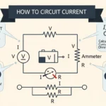


Imagine you switch on a light in your home, but nothing happens. The bulb is fine, the switch seems okay, yet there’s no light. How do you find the problem? This is where circuit analysis becomes essential.
Circuit analysis is the process engineers use to understand how electrical circuits behave. It helps you determine current, voltage, and power in different parts of a circuit. Without it, designing or troubleshooting electrical systems would be guesswork.
For students, engineers, and technicians, learning What is Circuit Analysis is a core skill. It forms the foundation for working with electronics, power systems, and control systems.
In this article, you will learn the circuit analysis working principle, types, main components, real-world applications, and practical troubleshooting methods. By the end, you will have a clear and confident understanding of how to analyze any basic electrical circuit.
2. What is Circuit Analysis? (2026)
Circuit analysis is the systematic process of studying an electrical circuit to determine unknown electrical quantities such as current (I), voltage (V), resistance (R), power (P), and energy consumption. It involves applying fundamental electrical laws, mathematical equations, and analytical techniques to understand how electricity flows through different components of a circuit.
Whether the circuit is simple with just a battery and resistor or a complex network containing multiple power sources, resistors, capacitors, inductors, and semiconductor devices, circuit analysis helps engineers predict the circuit’s behavior before it is built or modified.
In electrical engineering, circuit analysis is one of the most important skills because it allows engineers and technicians to design safe, efficient, and reliable electrical systems. It is widely used in residential wiring, industrial automation, electronic devices, communication systems, renewable energy systems, electric vehicles, and power distribution networks.
Simple Explanation
Think of an electrical circuit as a road network and electricity as vehicles traveling on that road. Just as traffic engineers analyze the movement of vehicles to prevent congestion, electrical engineers analyze the flow of electric current to ensure that every component receives the correct amount of voltage and current.
Circuit analysis is similar to solving a puzzle. Some values are already known, such as the supply voltage or resistance, while other values are unknown. By applying electrical laws and formulas, you can calculate these unknown values accurately.
For example, if you know the battery voltage and the resistance of a resistor, circuit analysis helps you determine:
- The current flowing through the circuit.
- The voltage across each component.
- The power consumed by the resistor.
- The total resistance of the circuit.
- The overall efficiency of the electrical system.
This process enables engineers to verify whether a circuit will operate correctly before it is physically constructed.
Practical Example
Imagine you have a 12-volt battery connected to a 6-ohm resistor in a simple series circuit.
Using Ohm’s Law:
Current (I) = Voltage (V) ÷ Resistance (R)
Current = 12V ÷ 6Ω = 2A
Now you can also calculate the power consumed by the resistor:
Power (P) = Voltage × Current
Power = 12 × 2 = 24 Watts
Through circuit analysis, you can quickly determine:
- Supply voltage = 12 V
- Resistance = 6 Ω
- Current flowing = 2 A
- Power consumption = 24 W
Without circuit analysis, these important electrical values would remain unknown, making it difficult to design or troubleshoot the circuit.
Why Circuit Analysis is Important
Circuit analysis is essential because it helps engineers and technicians:
- Calculate current, voltage, resistance, and power accurately.
- Design safe and efficient electrical circuits.
- Detect and troubleshoot electrical faults quickly.
- Prevent overloads, short circuits, and equipment damage.
- Improve the performance and efficiency of electrical systems.
- Select the correct electrical components for a specific application.
- Verify circuit designs before manufacturing or installation.
Where Circuit Analysis is Used
Circuit analysis is used in almost every field of electrical and electronic engineering, including:
- Residential electrical wiring
- Commercial and industrial power systems
- Electronic circuit design
- Solar photovoltaic (PV) systems
- Electric vehicles (EVs)
- Power transmission and distribution
- Robotics and automation
- Telecommunications
- Consumer electronics
- Medical equipment
- Aerospace and defense systems
In Simple Words
Circuit analysis is the process of examining an electrical circuit to calculate unknown values such as current, voltage, resistance, and power. By applying electrical laws like Ohm’s Law and Kirchhoff’s Laws, engineers can understand how electricity flows, predict circuit behavior, ensure safety, troubleshoot faults, and design reliable electrical and electronic systems.
3. Working Principle of Circuit Analysis (2026)
The working principle of circuit analysis is based on applying fundamental electrical laws and mathematical equations to determine how electrical current and voltage behave within a circuit. By analyzing the relationship between the power source, electrical components, and connecting conductors, engineers can calculate unknown values such as current, voltage, resistance, power, and energy.
Every electrical circuit follows specific physical laws. Circuit analysis uses these laws to understand the path of current flow, the voltage across each component, and how electrical energy is distributed throughout the circuit. Whether the circuit is simple or highly complex, the same analytical process is followed to predict its behavior accurately.
Key Electrical Laws Used in Circuit Analysis
Circuit analysis mainly relies on three fundamental electrical laws.
1. Ohm’s Law
Ohm’s Law defines the relationship between voltage, current, and resistance.
Formula:
V = I × R
Where:
- V = Voltage (Volts)
- I = Current (Amperes)
- R = Resistance (Ohms)
This law helps calculate any one electrical quantity when the other two are known. It is the foundation of almost every circuit analysis problem.
2. Kirchhoff’s Current Law (KCL)
Kirchhoff’s Current Law states that the total current entering a junction is always equal to the total current leaving the junction.
Formula:
ΣI(in) = ΣI(out)
KCL is mainly used for analyzing parallel circuits and electrical networks with multiple branches.
3. Kirchhoff’s Voltage Law (KVL)
Kirchhoff’s Voltage Law states that the algebraic sum of all voltages around any closed loop is always zero.
Formula:
ΣV = 0
KVL is widely used for solving series circuits and complex loop networks.
Step-by-Step Working Process of Circuit Analysis
Step 1: Identify All Circuit Components
The first step is to examine the circuit diagram carefully and identify every electrical component.
These may include:
- Voltage sources
- Current sources
- Resistors
- Capacitors
- Inductors
- Switches
- Wires and junctions
Understanding the type and arrangement of each component makes the analysis easier.
Step 2: Determine the Circuit Configuration
Next, determine how the components are connected.
Common circuit configurations include:
- Series circuits
- Parallel circuits
- Series-parallel circuits
- Mesh networks
- Bridge circuits
The analysis method depends on the circuit configuration.
Step 3: Assign Current Direction and Voltage Polarity
Before writing equations, assume the direction of current flow and assign voltage polarity across each component.
Even if the assumed direction is incorrect, the mathematical solution will indicate the correct direction by producing a negative value.
Step 4: Apply Fundamental Electrical Laws
Use the appropriate electrical laws based on the circuit.
- Apply Ohm’s Law to calculate voltage, current, or resistance.
- Apply Kirchhoff’s Current Law (KCL) at electrical junctions.
- Apply Kirchhoff’s Voltage Law (KVL) around closed loops.
These laws form the basis of all circuit calculations.
Step 5: Write Mathematical Equations
Using the known circuit values and electrical laws, write equations for every loop or node.
These equations represent the electrical behavior of the circuit and help determine the unknown quantities.
Step 6: Solve the Equations
Solve the mathematical equations using algebraic methods or circuit analysis techniques such as:
- Nodal Analysis
- Mesh Analysis
- Superposition Theorem
- Thevenin’s Theorem
- Norton’s Theorem
The solution provides values for:
- Current
- Voltage
- Resistance
- Power
- Energy
Step 7: Verify the Results
Finally, verify that the calculated values satisfy all electrical laws.
Check that:
- Kirchhoff’s Current Law is satisfied at every node.
- Kirchhoff’s Voltage Law is satisfied in every loop.
- The calculated current and voltage values are physically reasonable.
- Power supplied equals power consumed.
This verification ensures the accuracy of the analysis.
Practical Example
Suppose a 24 V battery is connected to two resistors of 4 Ω and 8 Ω in series.
Step 1: Calculate total resistance.
R = 4 Ω + 8 Ω = 12 Ω
Step 2: Calculate current using Ohm’s Law.
I = V ÷ R = 24 ÷ 12 = 2 A
Step 3: Calculate voltage across each resistor.
- Voltage across 4 Ω resistor = 2 × 4 = 8 V
- Voltage across 8 Ω resistor = 2 × 8 = 16 V
Step 4: Verify using Kirchhoff’s Voltage Law.
8 V + 16 V = 24 V ✓
This confirms that the circuit analysis is correct.
Easy Analogy
Imagine a water pipeline system:
- Voltage is like the water pressure pushing water through the pipes.
- Current is like the amount of water flowing through the pipes.
- Resistance is like a narrow pipe or valve that restricts water flow.
- Power Source is like a water pump supplying pressure.
Circuit analysis works much like calculating how water moves through a network of pipes. By knowing the pressure, pipe size, and flow restrictions, you can predict how much water will flow through each section. Similarly, circuit analysis determines how electricity flows through an electrical circuit and how each component affects the overall system.
4. Types of Circuit Analysis (2026)
Circuit analysis can be classified in several ways depending on the type of electrical circuit, the nature of the electrical supply, and the mathematical method used to solve the circuit. Each type of circuit analysis has its own advantages and is suitable for specific electrical and electronic applications.
Understanding these different types helps students, engineers, and technicians choose the most effective analysis technique for solving electrical problems accurately.
Types of Circuit Analysis Based on Circuit Nature
The most common classification is based on the type of electrical current flowing through the circuit.
DC Circuit Analysis
DC (Direct Current) Circuit Analysis is used to study circuits powered by a direct current source, where the current flows in only one direction and the voltage remains constant over time.
Because the electrical values do not change continuously, DC circuit analysis is generally simpler than AC circuit analysis. Engineers mainly use Ohm’s Law, Kirchhoff’s Laws, and network theorems to determine current, voltage, resistance, and power.
Characteristics
- Current flows in one direction only.
- Voltage remains constant.
- Frequency is zero (0 Hz).
- Simple mathematical calculations.
- Stable electrical parameters.
Applications
- Battery-powered devices
- Solar photovoltaic systems
- Electric vehicles
- LED lighting circuits
- Portable electronic devices
- DC motors
- Industrial control circuits
Advantages
- Easy to analyze and troubleshoot.
- Requires simple mathematical calculations.
- Ideal for beginners learning circuit analysis.
- Highly reliable for low-voltage applications.
AC Circuit Analysis
AC (Alternating Current) Circuit Analysis deals with electrical circuits where the current and voltage continuously change in both magnitude and direction with time.
Unlike DC circuits, AC analysis must consider additional factors such as frequency, phase angle, reactance, impedance, and power factor. These factors make AC circuit analysis more complex but essential for modern electrical power systems.
Characteristics
- Current changes direction periodically.
- Voltage varies continuously.
- Includes frequency and phase angle.
- Uses impedance instead of only resistance.
- Involves inductive and capacitive effects.
Applications
- Residential electrical wiring
- Commercial buildings
- Industrial power systems
- Transmission and distribution networks
- Air conditioners
- Transformers
- Induction motors
- Household appliances
Advantages
- Suitable for large-scale power transmission.
- Supports transformers for voltage conversion.
- Widely used in modern electrical systems.
- Efficient for long-distance electricity distribution.
Types of Circuit Analysis Based on Analysis Methods
Electrical engineers use different mathematical techniques depending on the complexity of the circuit.
1. Nodal Analysis
Nodal Analysis is a systematic method used to determine the voltage at different nodes of an electrical circuit. It is based on Kirchhoff’s Current Law (KCL), which states that the total current entering a node is equal to the total current leaving the node.
Instead of calculating loop currents, nodal analysis focuses on unknown node voltages, making it highly effective for circuits with many parallel branches.
Working Principle
- Identify all circuit nodes.
- Select one node as the reference (ground).
- Assign voltages to the remaining nodes.
- Apply Kirchhoff’s Current Law at each node.
- Solve the resulting equations to find the unknown voltages.
Advantages
- Best for circuits with multiple current sources.
- Reduces the number of equations in complex circuits.
- Highly accurate and systematic.
- Widely used in circuit simulation software.
Applications
- Electronic circuit design
- Power system analysis
- Communication systems
- Computer circuit design
- Integrated circuits (ICs)
2. Mesh Analysis
Mesh Analysis is a loop-based circuit analysis technique that determines the current flowing through each independent loop of a circuit. It is based on Kirchhoff’s Voltage Law (KVL), which states that the algebraic sum of all voltages around a closed loop is zero.
Mesh analysis is especially useful for planar circuits, where circuit branches do not cross each other.
Working Principle
- Identify independent loops (meshes).
- Assign a loop current to each mesh.
- Apply Kirchhoff’s Voltage Law around every loop.
- Write simultaneous equations.
- Solve the equations to determine loop currents.
Advantages
- Simple for planar circuits.
- Requires fewer equations than some other methods.
- Produces accurate current calculations.
- Easy to understand for series-loop circuits.
Applications
- Electrical network analysis
- PCB circuit design
- Analog electronics
- Industrial electrical systems
3. Thevenin’s Theorem
Thevenin’s Theorem is a powerful circuit simplification technique that converts a complex linear electrical network into an equivalent circuit consisting of a single voltage source (Thevenin Voltage, Vₜₕ) in series with an equivalent resistance (Thevenin Resistance, Rₜₕ).
This method greatly simplifies calculations when analyzing different load conditions.
Working Principle
- Remove the load resistor.
- Calculate the open-circuit voltage (Vₜₕ).
- Determine the equivalent resistance (Rₜₕ).
- Replace the original network with the simplified equivalent circuit.
- Reconnect the load and calculate the required values.
Advantages
- Simplifies complex circuits.
- Saves calculation time.
- Easy to analyze varying load conditions.
- Reduces complicated networks to a simple equivalent circuit.
Applications
- Power system design
- Electronic circuit analysis
- Load optimization
- Electrical network simplification
- Circuit troubleshooting
4. Norton’s Theorem
Norton’s Theorem is another circuit simplification technique that converts a complex linear circuit into an equivalent circuit containing a current source (Norton Current, Iₙ) in parallel with an equivalent resistance (Norton Resistance, Rₙ).
It is mathematically equivalent to Thevenin’s Theorem but is often preferred when analyzing current-driven circuits.
Working Principle
- Remove the load resistor.
- Calculate the short-circuit current (Iₙ).
- Determine the equivalent resistance (Rₙ).
- Replace the original circuit with the Norton equivalent.
- Reconnect the load and calculate the required electrical quantities.
Advantages
- Simplifies current-source circuits.
- Makes current calculations easier.
- Equivalent to Thevenin’s method.
- Reduces analysis time for complex networks.
Applications
- Current-source networks
- Electronic circuit design
- Industrial electrical systems
- Power electronics
- Network analysis
5. Superposition Theorem
The Superposition Theorem is used to analyze linear circuits that contain multiple independent voltage and current sources. According to this theorem, the total voltage or current in any element is equal to the algebraic sum of the contributions produced by each independent source acting alone.
Advantages
- Simplifies multi-source circuits.
- Makes complex calculations more manageable.
- Helps understand the contribution of each source individually.
Applications
- Multi-source electrical networks
- Analog circuit design
- Communication systems
- Signal processing circuits
6. Maximum Power Transfer Theorem
The Maximum Power Transfer Theorem states that the maximum amount of power is delivered to the load when the load resistance is equal to the source’s internal (Thevenin) resistance.
Applications
- Audio amplifiers
- Communication systems
- Impedance matching
- RF circuits
- Power electronics
Comparison of Different Circuit Analysis Methods
| Analysis Method | Primary Law Used | Best For | Main Output |
|---|---|---|---|
| DC Circuit Analysis | Ohm’s Law, KCL, KVL | Constant voltage circuits | Current, Voltage, Power |
| AC Circuit Analysis | Ohm’s Law, Phasor Analysis | Alternating current systems | Impedance, Phase Angle |
| Nodal Analysis | Kirchhoff’s Current Law (KCL) | Parallel and complex circuits | Node Voltages |
| Mesh Analysis | Kirchhoff’s Voltage Law (KVL) | Planar loop circuits | Loop Currents |
| Thevenin’s Theorem | Network Theorems | Circuit simplification | Equivalent Voltage Source |
| Norton’s Theorem | Network Theorems | Current-source circuits | Equivalent Current Source |
| Superposition Theorem | Linear Circuit Principle | Multiple-source circuits | Individual Source Contribution |
| Maximum Power Transfer | Power Transfer Principle | Load optimization | Maximum Load Power |
By understanding these types of circuit analysis, engineers can select the most appropriate technique to solve electrical circuits efficiently, whether they are working with simple DC networks, complex AC systems, or advanced electronic circuits.
5. Main Components Used in Circuit Analysis (2026)
To perform circuit analysis accurately, it is essential to understand the main electrical components that make up an electrical circuit. Each component has a specific function and influences how current flows, how voltage is distributed, and how electrical energy is stored or consumed.
During circuit analysis, engineers examine the behavior of these components to calculate unknown electrical quantities such as current, voltage, resistance, power, and energy. Whether analyzing a simple DC circuit or a complex AC network, these components form the foundation of every electrical system.
1. Voltage Source
A voltage source is the component that supplies electrical energy to a circuit by creating a potential difference between two terminals. It is the driving force that causes electric current to flow through the circuit.
Voltage sources can be either DC (Direct Current) or AC (Alternating Current) depending on the application.
Types of Voltage Sources
- DC Battery
- DC Power Supply
- AC Generator
- AC Mains Supply
- Solar Panel
Functions
- Supplies electrical energy.
- Creates the voltage difference required for current flow.
- Powers electrical and electronic devices.
- Maintains the required operating voltage.
Applications
- Mobile phones
- Laptops
- Household electrical systems
- Industrial machinery
- Solar energy systems
- Electric vehicles
2. Current Source
A current source supplies a constant amount of electric current regardless of changes in circuit resistance (within its operating limits). It is commonly used in electronic circuits and circuit analysis problems.
Functions
- Maintains constant current.
- Drives electronic circuits.
- Used in testing and simulation.
Applications
- LED drivers
- Current mirrors
- Electronic testing equipment
- Integrated circuits
3. Resistor
A resistor is a passive electrical component that limits the flow of electric current. It converts a portion of electrical energy into heat and helps control current and voltage within a circuit.
Resistors are one of the most commonly analyzed components in electrical engineering.
Functions
- Limits current flow.
- Produces voltage drops.
- Protects sensitive components.
- Controls power consumption.
- Divides voltage in resistor networks.
Types of Resistors
- Fixed Resistor
- Variable Resistor (Potentiometer)
- Thermistor
- Light Dependent Resistor (LDR)
Applications
- Electronic circuits
- Voltage dividers
- LED current limiting
- Control systems
- Sensor circuits
4. Capacitor
A capacitor is a passive component that stores electrical energy in the form of an electric field. It charges when connected to a power source and discharges when the stored energy is needed.
Capacitors play a major role in both DC and AC circuit analysis.
Functions
- Stores electrical energy temporarily.
- Filters unwanted electrical noise.
- Smooths power supply output.
- Blocks DC while allowing AC signals.
- Provides timing functions.
Types of Capacitors
- Ceramic Capacitor
- Electrolytic Capacitor
- Film Capacitor
- Tantalum Capacitor
- Variable Capacitor
Applications
- Power supplies
- Signal filtering
- Audio circuits
- Motor starting circuits
- Communication systems
5. Inductor
An inductor is a passive electrical component that stores energy in the form of a magnetic field when current flows through its coil. It opposes sudden changes in current, making it important in AC circuits and power electronics.
Functions
- Stores magnetic energy.
- Opposes rapid changes in current.
- Filters electrical signals.
- Reduces electrical noise.
- Stabilizes current flow.
Types of Inductors
- Air Core Inductor
- Iron Core Inductor
- Ferrite Core Inductor
- Toroidal Inductor
Applications
- Transformers
- Power supplies
- Filters
- DC-DC converters
- Radio frequency circuits
6. Switch
A switch is a control device used to open or close an electrical circuit. It allows users to start or stop the flow of current whenever required.
Functions
- Turns circuits ON and OFF.
- Controls current flow.
- Protects electrical equipment.
- Provides circuit isolation during maintenance.
Applications
- Home electrical wiring
- Industrial control panels
- Consumer electronics
- Automation systems
7. Conducting Wires and Connections
Electrical wires and conductors provide the path through which electric current travels between different circuit components. In ideal circuit analysis, wires are assumed to have zero resistance, although real conductors have a small amount of resistance.
Functions
- Connect electrical components.
- Carry current safely.
- Complete the electrical circuit.
- Minimize energy loss.
Common Conducting Materials
- Copper
- Aluminum
- Silver (special applications)
Applications
- Power transmission
- Building wiring
- Electronic devices
- Industrial installations
8. Ground (Earth)
The ground or earth serves as the reference point for measuring voltage in a circuit. It also provides a safe path for fault current, helping to protect people and equipment from electrical hazards.
Functions
- Acts as a voltage reference.
- Improves electrical safety.
- Protects against electric shock.
- Stabilizes circuit operation.
Applications
- Residential wiring
- Industrial electrical systems
- Electronic circuits
- Power distribution networks
9. Measuring Instruments
Measuring instruments are essential for performing circuit analysis because they allow engineers and technicians to measure electrical quantities accurately.
Voltmeter
A voltmeter measures the voltage or potential difference between two points in a circuit.
Applications
- Checking battery voltage
- Measuring supply voltage
- Testing electrical equipment
Ammeter
An ammeter measures the amount of electric current flowing through a circuit.
Applications
- Measuring load current
- Monitoring motor current
- Electrical testing
Ohmmeter
An ohmmeter measures the electrical resistance of a component or conductor.
Applications
- Testing resistors
- Checking cable continuity
- Troubleshooting circuits
Digital Multimeter (DMM)
A digital multimeter combines the functions of a voltmeter, ammeter, and ohmmeter into a single instrument, making it one of the most widely used tools for circuit analysis.
Applications
- Electrical troubleshooting
- Electronic circuit testing
- Maintenance and repair
- Industrial inspections
Summary Table of Main Components Used in Circuit Analysis
| Component | Primary Function | Common Applications |
|---|---|---|
| Voltage Source | Supplies electrical energy | Batteries, power supplies, generators |
| Current Source | Supplies constant current | Electronic circuits, testing |
| Resistor | Limits current flow | Voltage dividers, protection circuits |
| Capacitor | Stores electrical energy | Filters, timing circuits, power supplies |
| Inductor | Stores magnetic energy | Filters, transformers, converters |
| Switch | Opens or closes a circuit | Electrical control and protection |
| Conducting Wires | Carry electric current | Wiring and circuit connections |
| Ground (Earth) | Provides reference and safety | Electrical installations and electronics |
| Voltmeter | Measures voltage | Circuit testing |
| Ammeter | Measures current | Electrical measurements |
| Ohmmeter | Measures resistance | Component testing |
| Digital Multimeter | Measures multiple electrical quantities | Troubleshooting and maintenance |
Understanding these main components of circuit analysis is essential because every electrical circuit is built using one or more of these elements. Knowing how each component behaves enables engineers and technicians to analyze circuits accurately, troubleshoot faults efficiently, and design safe, reliable, and high-performance electrical systems.
6. Advantages of Circuit Analysis (2026)
Circuit analysis is one of the most important tools in electrical and electronic engineering. It allows engineers, technicians, and students to understand how electrical circuits operate before they are physically built or modified. By using mathematical models and electrical laws, circuit analysis improves the accuracy, safety, and efficiency of electrical systems.
Whether designing a simple household circuit or a large industrial power network, circuit analysis helps predict circuit performance, identify potential problems, and optimize system operation.
1. Enables Accurate Circuit Design
Circuit analysis helps engineers calculate the correct values of voltage, current, resistance, power, and energy before constructing a circuit. This ensures that every component is selected correctly and operates within its safe limits.
Benefits
- Improves design accuracy.
- Prevents component failure.
- Reduces design errors.
- Ensures reliable circuit operation.
2. Simplifies Troubleshooting
One of the biggest advantages of circuit analysis is that it helps locate electrical faults quickly. By comparing calculated values with actual measurements, technicians can identify faulty components or wiring problems without unnecessary trial and error.
Benefits
- Faster fault detection.
- Reduced maintenance time.
- Easier equipment repair.
- Improved system reliability.
3. Improves System Efficiency
Circuit analysis enables engineers to optimize the flow of electrical power, reducing unnecessary energy losses. Efficient circuit design lowers power consumption while maintaining the desired performance.
Benefits
- Reduces power losses.
- Improves energy efficiency.
- Increases overall system performance.
- Supports energy-saving designs.
4. Enhances Electrical Safety
Proper circuit analysis helps prevent electrical hazards such as overloading, overheating, short circuits, and excessive current flow. Engineers can verify that every component operates within its rated capacity.
Benefits
- Prevents equipment damage.
- Reduces fire risks.
- Protects users from electrical shock.
- Increases system safety.
5. Saves Time and Project Costs
By identifying design issues before installation, circuit analysis minimizes costly modifications, repeated testing, and unnecessary material usage. This significantly reduces both development time and project expenses.
Benefits
- Lowers development costs.
- Reduces material waste.
- Speeds up project completion.
- Minimizes redesign efforts.
6. Predicts Circuit Behavior Before Construction
Engineers can simulate and analyze circuit performance before building the actual system. This allows them to evaluate different design options and make improvements without physical prototypes.
Benefits
- Predicts circuit performance.
- Reduces design risks.
- Supports simulation-based engineering.
- Improves product quality.
7. Supports Complex Electrical System Design
Modern electrical systems often contain hundreds or thousands of interconnected components. Circuit analysis provides systematic methods such as Nodal Analysis, Mesh Analysis, Thevenin’s Theorem, and Norton’s Theorem to simplify complex calculations.
Benefits
- Handles large electrical networks.
- Simplifies complicated circuits.
- Improves calculation accuracy.
- Supports advanced engineering projects.
8. Essential for Modern Electrical Engineering
Circuit analysis is a fundamental skill used in nearly every area of electrical and electronics engineering.
Applications include:
- Power generation
- Power transmission
- Industrial automation
- Consumer electronics
- Renewable energy systems
- Electric vehicles
- Robotics
- Communication systems
- Medical equipment
- Aerospace technology
Summary of Advantages
- Accurate circuit design and analysis.
- Faster troubleshooting and fault detection.
- Improved energy efficiency.
- Enhanced electrical safety.
- Reduced project costs and development time.
- Predicts circuit performance before implementation.
- Simplifies complex electrical networks.
- Essential for modern electrical and electronic engineering.
7. Disadvantages and Limitations of Circuit Analysis (2026)
Although circuit analysis is an essential engineering tool, it also has certain limitations. Some electrical circuits become extremely difficult to analyze manually due to their size, complexity, and the non-ideal behavior of real-world components. Engineers often rely on simulation software and advanced computational methods to overcome these challenges.
Understanding these limitations helps in selecting the most appropriate analysis technique for a particular electrical system.
1. Complex for Large Electrical Circuits
As the number of components, loops, and nodes increases, the mathematical calculations become much more complicated. Large industrial and electronic circuits often require advanced analysis methods and specialized software.
Limitations
- Large number of equations.
- Difficult manual calculations.
- Increased analysis time.
2. Requires Strong Knowledge of Electrical Fundamentals
Successful circuit analysis depends on a solid understanding of basic electrical concepts such as:
- Ohm’s Law
- Kirchhoff’s Current Law (KCL)
- Kirchhoff’s Voltage Law (KVL)
- Network Theorems
- AC and DC circuit principles
Without this foundation, solving electrical circuits accurately becomes difficult.
3. Time-Consuming Manual Calculations
For simple circuits, manual calculations are straightforward. However, analyzing complex networks with many nodes and loops can take considerable time if performed without computer software.
Challenges
- Lengthy mathematical procedures.
- Multiple simultaneous equations.
- Higher probability of calculation mistakes.
4. Assumptions May Reduce Accuracy
Circuit analysis often assumes ideal conditions, such as:
- Ideal voltage sources.
- Zero-resistance wires.
- Ideal resistors, capacitors, and inductors.
- Constant temperature.
In practical applications, these assumptions are not always valid, which may cause small differences between calculated and actual results.
5. Real Components Are Not Ideal
Actual electrical components exhibit characteristics that are not included in basic circuit models.
Examples include:
- Internal resistance in batteries.
- Wire resistance.
- Capacitor leakage current.
- Inductor core losses.
- Temperature-dependent resistance.
These factors can affect circuit performance and reduce the accuracy of theoretical calculations.
6. Limited for Highly Nonlinear Circuits
Basic circuit analysis methods are mainly designed for linear circuits. Circuits containing semiconductor devices such as transistors, diodes, and integrated circuits often require advanced nonlinear analysis techniques.
Examples
- Power electronic converters.
- Digital circuits.
- Switching circuits.
- Microprocessor-based systems.
7. Requires Computer Software for Advanced Systems
Modern electrical systems may contain thousands of interconnected components. Manual analysis becomes impractical, making software tools essential.
Common circuit simulation software includes:
- MATLAB/Simulink
- LTspice
- PSpice
- Multisim
- Proteus
Although these tools improve accuracy, they require additional training and expertise.
Summary of Limitations
- Difficult to analyze very large and complex circuits manually.
- Requires a strong understanding of electrical laws and mathematics.
- Manual calculations can be time-consuming.
- Incorrect assumptions may produce inaccurate results.
- Real-world components differ from ideal models.
- Basic methods are less suitable for nonlinear electronic circuits.
- Advanced systems often require specialized simulation software.
Despite these limitations, circuit analysis remains one of the most essential techniques in electrical engineering, providing the foundation for designing, analyzing, troubleshooting, and optimizing electrical and electronic systems.
8. Applications of Circuit Analysis (2026)
Circuit analysis is one of the most widely used techniques in electrical and electronic engineering. It is applied wherever electrical circuits are designed, tested, installed, operated, or maintained. By analyzing current, voltage, resistance, power, and energy flow, engineers can ensure that electrical systems work safely, efficiently, and reliably.
From simple household appliances to advanced aerospace systems, circuit analysis plays a vital role in the design, operation, and troubleshooting of modern technology.
Residential (Home) Applications
Circuit analysis is extensively used in residential electrical installations to ensure safe wiring, efficient power distribution, and reliable operation of household appliances.
Electrical Wiring Design
Engineers use circuit analysis to determine the correct wire size, circuit breaker rating, and load capacity for homes.
Applications
- House wiring design
- Lighting circuits
- Socket outlet circuits
- Distribution boards
- Electrical renovations
Appliance Troubleshooting
When household appliances stop working, technicians use circuit analysis to locate faulty components such as switches, fuses, resistors, capacitors, or damaged wiring.
Applications
- Refrigerators
- Air conditioners
- Washing machines
- Microwave ovens
- Water heaters
- Ceiling fans
Power Consumption Calculation
Circuit analysis helps homeowners and electricians calculate the electrical power consumed by different appliances, making it easier to manage electricity usage and reduce energy bills.
Applications
- Load calculation
- Energy management
- Electrical bill estimation
- Home energy audits
Electrical Safety
Proper circuit analysis helps prevent electrical hazards by identifying overloaded circuits, voltage drops, and potential short circuits before they cause damage.
Applications
- Overload protection
- Circuit breaker selection
- Grounding system design
- Fire hazard prevention
Industrial Applications
Industries rely heavily on circuit analysis to operate complex electrical systems safely and efficiently.
Machine Control Systems
Industrial machines contain motors, sensors, relays, and controllers that require accurate circuit analysis for proper operation and maintenance.
Applications
- Motor control circuits
- Conveyor systems
- PLC-based automation
- Manufacturing equipment
- Robotics
Power Distribution Systems
Factories and commercial buildings use circuit analysis to design and maintain electrical distribution systems that deliver power safely to different loads.
Applications
- Distribution panels
- Switchgear
- Busbar systems
- Transformers
- Industrial substations
Fault Detection and Troubleshooting
Engineers use circuit analysis to quickly locate electrical faults, reducing equipment downtime and maintenance costs.
Applications
- Short-circuit detection
- Open-circuit testing
- Equipment diagnostics
- Preventive maintenance
- Electrical inspections
Industrial Automation
Modern industries use programmable logic controllers (PLCs), sensors, actuators, and industrial communication systems that require continuous circuit analysis for reliable operation.
Applications
- Automated production lines
- Smart manufacturing
- Process control systems
- Industrial monitoring
Electronics and Consumer Devices
Circuit analysis is the foundation of electronic circuit design and product development.
Consumer Electronics
Engineers analyze electronic circuits before manufacturing devices to ensure performance, reliability, and energy efficiency.
Applications
- Smartphones
- Laptops
- Desktop computers
- Tablets
- Smart TVs
- Gaming consoles
- Smartwatches
Printed Circuit Board (PCB) Design
Every electronic product contains one or more printed circuit boards. Circuit analysis ensures that all components function correctly before production.
Applications
- PCB design
- Embedded systems
- Microcontroller circuits
- Integrated circuits (ICs)
Renewable Energy Systems
Renewable energy installations depend heavily on circuit analysis for efficient power generation and distribution.
Solar Power Systems
Circuit analysis helps determine:
- Solar panel connections
- Battery charging circuits
- Inverter performance
- Load calculations
- System efficiency
Wind Energy Systems
Engineers analyze wind turbine electrical circuits to maximize power generation and ensure stable operation.
Applications
- Wind generators
- Power converters
- Grid integration
- Energy storage systems
Electric Vehicles (EVs)
Modern electric vehicles contain sophisticated electrical and electronic systems that require advanced circuit analysis during design and maintenance.
Applications
- Battery Management Systems (BMS)
- Electric motor controllers
- Charging systems
- Power converters
- Regenerative braking systems
- Vehicle control electronics
Communication Systems
Communication networks depend on accurately designed electronic circuits to transmit and receive signals efficiently.
Applications
- Mobile communication
- Radio transmitters
- Television broadcasting
- Satellite communication
- Fiber optic equipment
- Internet networking devices
Medical Equipment
Modern healthcare equipment relies on precise circuit analysis to ensure safe and accurate operation.
Applications
- ECG machines
- MRI scanners
- X-ray systems
- Patient monitoring devices
- Infusion pumps
- Ventilators
Aerospace and Defense
Aircraft, spacecraft, and defense systems contain highly reliable electrical circuits that must be analyzed carefully to ensure maximum safety and performance.
Applications
- Aircraft electrical systems
- Satellite electronics
- Radar systems
- Navigation equipment
- Military communication systems
- Flight control systems
Education and Research
Circuit analysis is a core subject in electrical and electronics engineering education and research.
Applications
- Engineering laboratories
- University projects
- Circuit simulations
- Research and development
- Electrical training programs
Power Generation, Transmission, and Distribution
Electrical utilities use circuit analysis throughout the entire power system to maintain stability, efficiency, and reliability.
Applications
- Power plants
- Transmission lines
- Distribution networks
- Substations
- Protective relaying
- Grid monitoring
Robotics and Automation
Robotic systems combine electrical, electronic, and control circuits that require continuous analysis for accurate movement and decision-making.
Applications
- Industrial robots
- Autonomous vehicles
- Smart factories
- AI-powered automation
- Servo motor control
- Sensor integration
Summary of Circuit Analysis Applications
| Application Area | Common Uses |
|---|---|
| Residential | House wiring, appliance troubleshooting, load calculation, electrical safety |
| Industrial | Machine control, automation, fault detection, power distribution |
| Consumer Electronics | Smartphones, laptops, TVs, embedded systems, PCB design |
| Renewable Energy | Solar PV systems, wind turbines, battery storage, inverters |
| Electric Vehicles | Battery management, motor controllers, charging systems |
| Communication | Mobile networks, radio, satellite, fiber optics |
| Medical Equipment | ECG, MRI, X-ray, patient monitoring devices |
| Aerospace & Defense | Aircraft systems, radar, navigation, satellites |
| Power Systems | Generation, transmission, substations, distribution networks |
| Education & Research | Engineering labs, simulations, academic research |
| Robotics & Automation | Industrial robots, PLC systems, smart manufacturing |
Circuit analysis is an indispensable part of modern electrical engineering because it enables professionals to design, analyze, optimize, and troubleshoot electrical circuits across a wide range of industries. Its applications extend from everyday household appliances to advanced technologies such as renewable energy systems, electric vehicles, robotics, communication networks, medical equipment, aerospace, and intelligent power grids, making it one of the most fundamental concepts in the field of electrical and electronics engineering.
9. Comparison Section
Difference Between Circuit Analysis and Circuit Simulation
| Feature | Circuit Analysis | Circuit Simulation |
| Method | Manual calculation | Software-based |
| Accuracy | Depends on user | Highly accurate |
| Speed | Slower | Faster |
| Learning Value | Strong understanding | Less conceptual learning |
| Tools Required | Basic formulas | Computer software |
| Practical Use | Design and theory | Testing and validation |
10. How to Choose the Right Circuit Analysis Method (Selection Guide) (2026)
Selecting the appropriate circuit analysis method is essential for obtaining accurate results while minimizing calculation time and complexity. The best method depends on several factors, including the type of circuit, the number of components, the number of loops and nodes, the power source (AC or DC), and the level of accuracy required.
Simple circuits can often be solved using basic electrical laws, whereas large electrical networks require advanced analysis techniques such as Nodal Analysis, Mesh Analysis, or Network Theorems.
Use Basic Circuit Analysis When
Basic analysis techniques are ideal for simple electrical circuits containing only a few components.
Recommended For
- Simple series circuits
- Simple parallel circuits
- Basic DC circuits
- Educational laboratory experiments
- Beginner-level electrical problems
Best Methods
- Ohm’s Law
- Kirchhoff’s Current Law (KCL)
- Kirchhoff’s Voltage Law (KVL)
Advantages
- Easy to understand.
- Quick calculations.
- Minimal mathematical complexity.
- Perfect for beginners.
Use Nodal Analysis When
Nodal Analysis is the preferred method when circuits contain multiple nodes and several parallel branches.
Recommended For
- Complex parallel circuits
- Multiple current sources
- Electronic circuit design
- Large electrical networks
Advantages
- Reduces the number of equations.
- Highly efficient for parallel circuits.
- Widely used in circuit simulation software.
Use Mesh Analysis When
Mesh Analysis is most effective for planar circuits with multiple closed loops.
Recommended For
- Loop-based electrical circuits
- Planar resistor networks
- AC and DC loop circuits
Advantages
- Simple loop-current calculations.
- Excellent for series-connected networks.
- Produces accurate results.
Use Thevenin’s and Norton’s Theorems When
These network theorems simplify complex circuits into equivalent circuits, making repeated calculations much easier.
Recommended For
- Load analysis
- Circuit simplification
- Power system calculations
- Electronic circuit design
Advantages
- Simplifies complicated networks.
- Saves calculation time.
- Makes load changes easier to analyze.
Use AC Circuit Analysis When
AC analysis is required whenever the circuit contains alternating current, inductors, capacitors, transformers, or sinusoidal power sources.
Recommended For
- Household electrical systems
- Industrial power systems
- Motor circuits
- Power transmission networks
- Electronic filters
Important Concepts
- Frequency
- Phase angle
- Impedance
- Reactance
- Power factor
Use Circuit Simulation Software When
Very large electrical systems become difficult to solve manually. In such cases, engineers use specialized simulation software.
Popular Software
- MATLAB/Simulink
- LTspice
- PSpice
- Multisim
- Proteus
Advantages
- Faster calculations.
- High accuracy.
- Supports complex circuits.
- Reduces human error.
Tips for Beginners
If you are new to circuit analysis, follow these recommendations to build a strong foundation:
- Learn Ohm’s Law thoroughly before moving to advanced topics.
- Understand Kirchhoff’s Current Law (KCL) and Kirchhoff’s Voltage Law (KVL).
- Practice with simple series and parallel circuits first.
- Draw neat circuit diagrams before solving problems.
- Clearly label current directions and voltage polarities.
- Verify units such as volts (V), amperes (A), ohms (Ω), and watts (W).
- Double-check calculations to avoid arithmetic mistakes.
- Gradually learn advanced methods such as Nodal Analysis and Mesh Analysis.
- Use simulation software to compare your manual calculations with simulated results.
Quick Selection Table
| Circuit Type | Recommended Analysis Method |
|---|---|
| Simple DC Circuit | Ohm’s Law |
| Series Circuit | KVL + Ohm’s Law |
| Parallel Circuit | KCL + Ohm’s Law |
| Multiple Nodes | Nodal Analysis |
| Multiple Loops | Mesh Analysis |
| Complex Network | Thevenin’s or Norton’s Theorem |
| AC Circuit | AC Circuit Analysis |
| Large Industrial System | Simulation Software |
11. Common Problems in Circuit Analysis and Their Solutions (2026)
While performing circuit analysis, students and engineers often encounter calculation errors or incorrect results. Most of these problems occur because of incorrect assumptions, mathematical mistakes, or misunderstanding of electrical laws. Identifying these issues early helps improve both accuracy and troubleshooting skills.
Problem 1: Incorrect Current or Voltage Calculation
Cause
- Wrong formula selection.
- Incorrect resistance values.
- Calculation mistakes.
Solution
- Verify all given values.
- Apply the correct electrical law.
- Recalculate each step carefully.
- Check the final answer using an alternative method.
Problem 2: Wrong Units
Electrical calculations become incorrect when different units are mixed.
Common Mistakes
- Using milliamperes instead of amperes.
- Mixing kilohms with ohms.
- Confusing watts and kilowatts.
Solution
Always convert values into standard SI units before solving.
| Quantity | Standard Unit |
|---|---|
| Voltage | Volt (V) |
| Current | Ampere (A) |
| Resistance | Ohm (Ω) |
| Power | Watt (W) |
Problem 3: Difficulty Choosing Between Nodal and Mesh Analysis
Many beginners struggle to decide which method to use.
Use Nodal Analysis When
- The circuit has many nodes.
- Multiple current sources are present.
- Parallel branches dominate.
Use Mesh Analysis When
- The circuit has several loops.
- It is a planar circuit.
- Voltage sources are more common.
Problem 4: Confusing AC and DC Circuit Analysis
Many students apply DC formulas directly to AC circuits.
Difference
| DC Circuit Analysis | AC Circuit Analysis |
|---|---|
| Constant voltage and current | Voltage and current vary continuously |
| Uses resistance | Uses impedance |
| Frequency = 0 Hz | Includes frequency and phase angle |
| Simple calculations | More advanced calculations |
Problem 5: Violating Kirchhoff’s Laws
Incorrect equations often violate KCL or KVL.
Solution
- Check current entering and leaving every node.
- Ensure the sum of voltages around each closed loop equals zero.
- Review current directions and voltage polarities.
Problem 6: Incorrect Assumed Current Direction
Sometimes the assumed current direction is opposite to the actual direction.
Solution
This is not a serious error. A negative answer simply indicates that the actual current flows in the opposite direction.
Problem 7: Ignoring Real Component Behavior
Basic circuit analysis assumes ideal components, but real components have additional characteristics.
Examples include:
- Battery internal resistance.
- Capacitor leakage.
- Inductor winding resistance.
- Temperature effects.
Solution
For practical engineering work, include non-ideal component characteristics whenever necessary.
Problem 8: Relying Only on Simulation Software
Simulation software is extremely useful, but depending entirely on software without understanding the underlying theory can lead to mistakes.
Solution
- Learn manual circuit analysis first.
- Verify simulation results manually whenever possible.
- Use software as a verification tool rather than a replacement for fundamentals.
Frequently Asked Questions
Why am I getting incorrect answers?
Incorrect answers usually result from calculation mistakes, incorrect units, or applying the wrong electrical law. Always verify equations, units, and current directions before finalizing your solution.
How do I choose between Nodal Analysis and Mesh Analysis?
Use Nodal Analysis for circuits with many nodes and parallel branches. Use Mesh Analysis for planar circuits containing multiple loops.
What is the difference between DC and AC circuit analysis?
DC circuit analysis deals with constant voltage and current, while AC circuit analysis involves changing voltage and current, requiring concepts such as impedance, reactance, frequency, and phase angle.
Why is circuit analysis important?
Circuit analysis enables engineers to predict circuit behavior, improve efficiency, detect faults, ensure electrical safety, and design reliable electrical systems.
Can software replace manual circuit analysis?
No. Software improves speed and accuracy, but a strong understanding of manual circuit analysis is essential for troubleshooting, design, and engineering decision-making.
12. Future Trends in Circuit Analysis (2026)
As electrical engineering continues to evolve, circuit analysis is becoming more intelligent, automated, and data-driven. Modern engineers are combining traditional electrical principles with advanced computational technologies to solve increasingly complex electrical systems more efficiently.
The future of circuit analysis will be shaped by artificial intelligence, digital simulation, smart infrastructure, and intelligent electronic devices.
Artificial Intelligence (AI)-Assisted Circuit Design
Artificial Intelligence is transforming how engineers design and analyze electrical circuits. AI algorithms can automatically optimize component selection, identify design errors, and improve overall circuit performance.
Benefits
- Faster circuit optimization.
- Automatic fault detection.
- Reduced design time.
- Improved engineering productivity.
Advanced Circuit Simulation Software
Modern simulation tools provide highly accurate virtual testing environments where engineers can evaluate circuit performance before building physical prototypes.
Popular tools include:
- MATLAB/Simulink
- LTspice
- PSpice
- Multisim
- Proteus
Future software will offer real-time AI assistance, cloud-based collaboration, and automatic design optimization.
Smart Grid Technology
Future electrical power systems will rely heavily on intelligent smart grids that continuously monitor and optimize electricity distribution.
Circuit analysis will play a critical role in:
- Load balancing.
- Fault detection.
- Voltage regulation.
- Renewable energy integration.
- Grid stability.
Internet of Things (IoT) Integration
Billions of connected IoT devices require compact, low-power, and highly reliable electronic circuits. Circuit analysis will remain essential for designing energy-efficient IoT hardware.
Applications
- Smart homes
- Smart cities
- Industrial IoT
- Wearable electronics
- Remote monitoring systems
Electric Vehicles and Renewable Energy
The rapid growth of electric vehicles, solar power systems, wind farms, and battery storage technologies is increasing the demand for advanced circuit analysis techniques.
Future applications include:
- Battery Management Systems (BMS)
- High-efficiency inverters
- Fast EV charging stations
- Smart energy storage systems
High-Speed Electronics
Modern processors, 5G communication systems, and high-speed digital circuits require extremely accurate circuit analysis due to their high operating frequencies.
Future engineers will increasingly work with:
- High-speed PCB design
- RF circuits
- Microwave systems
- 5G and 6G communication networks
Digital Twins and Real-Time Monitoring
Digital Twin technology creates a virtual model of an electrical system that continuously receives data from the real system. Engineers can analyze performance, predict failures, and optimize operation without interrupting service.
Sustainable and Energy-Efficient Circuit Design
Future circuit analysis will place greater emphasis on reducing power consumption, improving energy efficiency, and supporting environmentally sustainable technologies.
This includes:
- Low-power electronic devices
- Green energy systems
- Energy-efficient industrial equipment
- Smart building automation
Future Outlook
The future of circuit analysis lies in the integration of artificial intelligence, advanced simulation software, smart grids, IoT, renewable energy systems, electric vehicles, digital twins, and high-speed electronics. While modern technologies continue to automate many engineering tasks, the fundamental principles of Ohm’s Law, Kirchhoff’s Laws, and network analysis will remain the backbone of electrical engineering. Engineers who combine strong theoretical knowledge with modern digital tools will be best prepared to design safer, smarter, and more efficient electrical systems in the years ahead.
13. Conclusion
Understanding What is Circuit Analysis is a key step in becoming a skilled electrical professional. It allows you to predict, design, and troubleshoot electrical circuits with confidence.
From simple DC circuits to complex AC systems, circuit analysis provides the tools needed to understand how electricity behaves. While it may seem challenging at first, consistent practice makes it easier.
The circuit analysis working principle, methods, and applications covered in this guide will help you build a strong foundation. Remember, mastering these basics is essential for advanced topics in electronics and power systems.
Keep practicing, stay curious, and continue exploring—this knowledge will support your growth throughout your electrical engineering journey.