
Imagine you are using a metal-bodied washing machine at home. Suddenly, due to a fault inside, the outer body becomes live. If you touch it, you could get a serious electric shock. But in most properly designed systems, this does not happen. Why? Because of earthing and grounding.
Earthing and grounding are essential safety systems used in electrical installations. They protect people, equipment, and buildings from electrical faults, leakage currents, and lightning. Without them, even a small fault could lead to dangerous situations like electric shock, fire, or equipment damage.
This topic is important for every electrical student, engineer, and technician because it is directly related to safety and system reliability. Understanding it helps you design safe systems, troubleshoot problems, and follow electrical standards correctly.
In this article, you will learn what earthing and grounding are, their working principle, types, components, advantages and disadvantages, applications, and the difference between earthing and grounding. By the end, you will have a clear and practical understanding of this critical concept.
What is Earthing and Grounding?
Earthing and grounding refer to connecting electrical systems to the earth (soil) to ensure safety and proper operation.
Definition
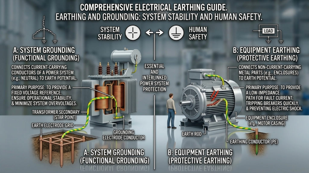
- Earthing: Connecting the non-current carrying parts (like metal body of equipment) to the earth
- Grounding: Connecting the current-carrying part (like neutral of transformer) to the earth
Simple Explanation
Earthing protects people from electric shock, while grounding stabilizes the electrical system.
Practical Example
- In a home, the metal body of an appliance is connected to earth wire → Earthing
- In a power system, the neutral point of transformer is connected to earth → Grounding
Working Principle
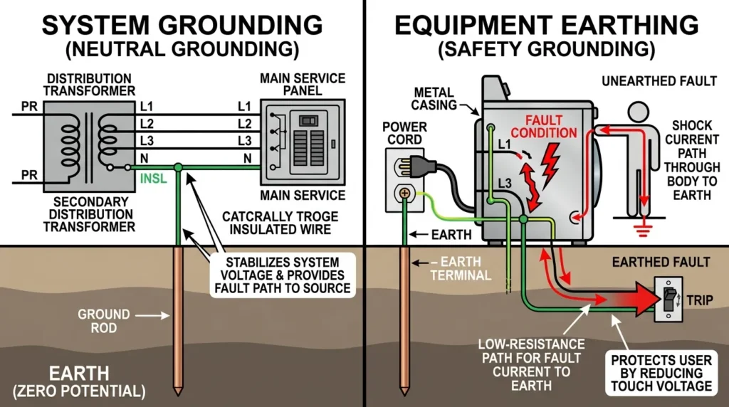
Earthing and grounding are safety methods used to protect people and electrical equipment from electric shock and fault currents. Their working principle is based on providing a low-resistance path for fault current to flow safely into the earth. During normal operation, no current flows through the earthing conductor. However, if an insulation failure or electrical fault occurs, the fault current flows through the earthing or grounding system instead of passing through a person or damaging equipment. This high fault current causes protective devices such as fuses, MCBs, MCCBs, or RCCBs to operate and disconnect the faulty circuit. Proper earthing and grounding improve electrical safety, stabilize system voltage, protect equipment from damage, and reduce the risk of fire and electric shock in residential, commercial, and industrial installations.
The earthing and grounding working principle is based on providing a low-resistance path for fault current to flow safely into the ground.
Step-by-Step Explanation
Fault occurs
- A live wire touches a metal body
Current finds alternate path
- Instead of flowing through a person, it flows through earth wire
Low resistance path
- Earth connection provides an easy path to the ground
Protection device operates
- Circuit breaker or fuse trips
System becomes safe
- Power is cut off, preventing harm
Easy Analogy
Think of it like a safety drain:
- Excess water flows safely through a drain
- Similarly, fault current flows safely into the earth
Key Points
- Earth has very low electrical potential
- Fault current always takes the easiest path
- Proper earthing ensures quick fault clearing
Types / Classification
Earthing and grounding can be classified into different types based on methods and applications.
Plate Earthing
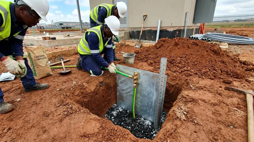
Plate Earthing is a common earthing method in which a copper or galvanized iron (GI) plate is buried vertically in the ground at a sufficient depth to provide a low-resistance path for fault current. The plate is surrounded by layers of charcoal (or coke) and salt to improve soil conductivity and maintain low earth resistance. An earthing conductor connects the plate to the electrical installation. During an electrical fault, the fault current flows safely through the plate into the earth, allowing protective devices such as fuses, MCBs, or RCCBs to operate and disconnect the faulty circuit. Plate earthing is widely used in residential, commercial, and industrial installations because it provides reliable grounding, improves electrical safety, and protects both people and equipment from electric shock and electrical faults.
- Uses a metal plate buried in the ground
- Plate is surrounded by charcoal and salt
- Common in residential systems
Pipe Earthing
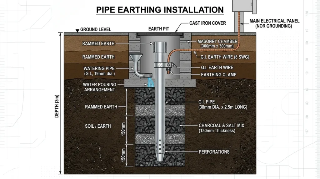
Pipe Earthing is the most commonly used method of earthing in electrical installations. In this method, a galvanized iron (GI) or copper pipe with small holes is buried vertically in the ground to provide a low-resistance path for fault current. The area around the pipe is filled with charcoal (or coke) and salt to improve soil conductivity and reduce earth resistance. An earthing conductor connects the pipe to the electrical system. During an electrical fault, the fault current flows safely through the pipe into the earth, causing protective devices such as fuses, MCBs, or RCCBs to trip and disconnect the faulty circuit. Pipe earthing is widely used in residential, commercial, and industrial installations because it is economical, reliable, easy to maintain, and provides effective protection against electric shock and equipment damage.
- Uses a perforated pipe buried vertically
- Most widely used method
- Cost-effective and efficient
Rod Earthing
- Uses a metal rod driven into the ground
- Suitable for rocky soil
- Easy to install
Strip or Wire Earthing
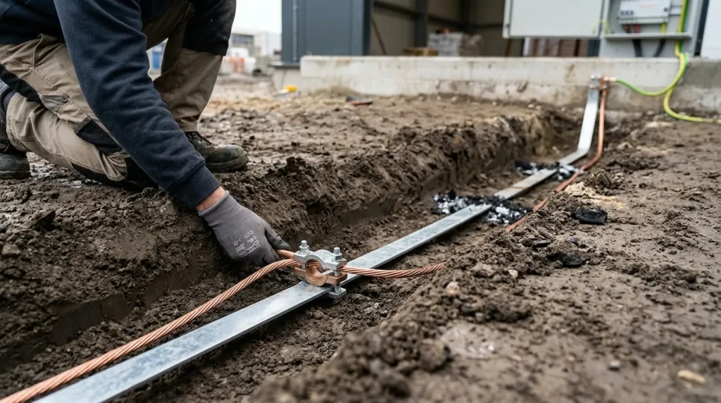
Strip or Wire Earthing is a method of earthing in which a metal strip or wire, usually made of copper or galvanized iron (GI), is buried underground to provide a low-resistance path for fault current. The strip or wire is connected between the electrical installation and the earth electrode, allowing leakage or fault current to flow safely into the ground. This type of earthing is commonly used in power distribution systems, substations, transmission lines, and industrial installations where a large area requires effective grounding. Strip or wire earthing provides reliable fault current dissipation, improves electrical safety, protects equipment from damage, and ensures the proper operation of protective devices.
- Uses metal strips buried in trenches
- Used in large installations
- Provides long grounding path
Chemical Earthing
- Uses special chemicals to reduce soil resistance
- Suitable for dry areas
- Provides stable performance
System Grounding Types
- Solid grounding
- Resistance grounding
- Reactance grounding
These are mainly used in power systems.
Main Components
Earthing and grounding systems consist of several important parts.
Earth Electrode
Metal plate, rod, or pipe buried in the ground.
Function: Transfers fault current to earth
Earth Wire (Conductor)
Connects equipment to electrode.
Function: Carries fault current safely
Earth Pit
Location where electrode is installed.
Function: Provides proper grounding environment
Charcoal and Salt
Used around electrode.
Function: Reduce soil resistance
Clamp and Connectors
Join wires and electrodes.
Function: Ensure strong and reliable connections
Advantages
Here are the key earthing and grounding advantages and disadvantages, starting with benefits:
- Protects humans from electric shock
- Prevents electrical fires
- Protects equipment from damage
- Ensures stable voltage levels
- Helps circuit breakers operate quickly
- Reduces risk during lightning strikes
- Improves system reliability
Disadvantages / Limitations
Despite its importance, there are some limitations:
- Installation cost can be high
- Requires regular maintenance
- Soil condition affects performance
- Corrosion can damage electrodes
- Poor installation reduces effectiveness
Applications
Earthing and grounding have wide applications in different sectors.
Home Applications
- Electrical wiring systems
- Appliances like refrigerators, washing machines
- Inverter and UPS systems
Industrial Applications
- Factories and machines
- Motor protection
- Control panels
Power Systems
- Transformers and generators
- Substations
- Transmission lines
Modern Technology
- Data centers
- Communication systems
- Solar and wind energy systems
- Electric vehicle charging stations
Comparison Section
Difference Between Earthing and Grounding
| Feature | Earthing | Grounding |
| Purpose | Protect humans | Protect system |
| Connection | Equipment body | Neutral or live part |
| Current Flow | Only during fault | Continuous or fault current |
| Usage | Homes and appliances | Power systems |
| Safety Role | Prevent electric shock | Stabilize voltage |
Understanding this difference between earthing and grounding is essential for proper system design.
Selection Guide
Choosing the right earthing system depends on various factors.
Tips for Beginners
- Check soil condition before installation
- Choose pipe earthing for general use
- Ensure low resistance (<5 ohms typically)
- Use proper quality materials
- Always follow safety standards
For Engineers
- Perform soil resistivity testing
- Select electrode type based on load
- Consider environmental conditions
- Plan for future expansion
- Ensure proper maintenance schedule
Common Problems & Solutions
Why do I get shock from appliances?
Improper earthing
Check and repair earth connection
What is high earth resistance?
Poor conductivity of soil
Add water, salt, or improve electrode
Why does earthing fail?
Corrosion or loose connections
Regular inspection and replacement
Can earthing be ignored?
No, it is essential for safety
How to test earthing?
Use earth resistance tester
Future Trends
Earthing and grounding systems are improving with new technologies.
Smart Grounding Systems
- Real-time monitoring
- Fault detection alerts
Advanced Materials
- Corrosion-resistant electrodes
- Longer life systems
Renewable Energy Systems
- Special grounding for solar and wind
- Improved safety for green energy
IoT Integration
- Remote monitoring of earthing performance
Improved Standards
- Stricter safety regulations
- Better global practices
Conclusion
Earthing and grounding are fundamental parts of any electrical system. They protect people from electric shock, safeguard equipment, and ensure stable operation. Without proper earthing, even a small fault can become dangerous.
Understanding the earthing and grounding working principle, types, applications, and limitations helps you design safer and more reliable systems. Knowing the difference between earthing and grounding is also important for proper implementation.
As a beginner or professional, always treat earthing as a priority, not an option. Good design, proper installation, and regular maintenance will ensure long-term safety and performance.