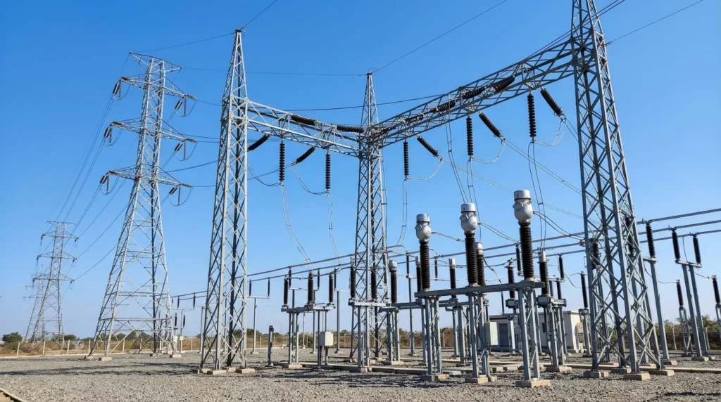

Imagine a large industrial area where factories, hospitals, schools, and thousands of homes depend on a continuous electricity supply. A power outage lasting only a few minutes can stop production lines, interrupt essential services, and cause significant financial losses. Behind the scenes, one of the most important facilities ensuring a stable power supply is the 33kV grid station.
A 33kV grid station acts as a bridge between high-voltage transmission lines and local electricity distribution networks. It receives electrical power from higher-voltage transmission systems, controls and protects it, and delivers electricity at 33 kilovolts (33kV) or steps it down further for safe distribution. Without these grid stations, modern cities and industries could not receive reliable electrical power.
Understanding the 33kV Grid Station Working Principle is essential for electrical engineering students, technicians, engineers, electricians, and anyone working with power systems. It provides a solid foundation for learning how electricity is transmitted, transformed, protected, and distributed safely.
In this comprehensive guide, you will learn the 33kV grid station working principle, types, major components, advantages and disadvantages, practical applications, comparisons with similar substations, selection tips, troubleshooting techniques, and future developments in electrical power distribution.
What is a 33kV Grid Station?
A 33kV grid station is an electrical substation that receives power from higher-voltage transmission lines, controls and protects the electrical supply, and distributes electricity at 33 kilovolts (33,000 volts) or reduces it to lower distribution voltages such as 11kV.
Its primary purpose is to ensure that electrical power is delivered safely, efficiently, and reliably to industries, commercial areas, and distribution substations.
In simple terms, a 33kV grid station is a power control and distribution center that manages electricity before it reaches consumers.
Practical Example
Suppose electricity is transmitted from a power plant at 132kV. Before it can be supplied to nearby cities or industrial zones, the voltage is reduced to 33kV at a grid station. From there, electricity is distributed to 11kV substations, which finally supply 400V/230V to homes and businesses.
33kV Grid Station Working Principle
The 33kV grid station working principle involves receiving high-voltage electrical power, controlling its flow, protecting the system against faults, and distributing electricity safely to lower-voltage networks.
The entire process is automatic and continuously monitored.
Receiving Electrical Power
Electricity enters the grid station through incoming transmission lines.
Typical incoming voltages include:
- 66kV
- 132kV
- 220kV
- Higher transmission voltages
Switching and Isolation
Before power enters the transformer, it passes through switching equipment such as circuit breakers and isolators.
These devices allow operators to safely connect or disconnect equipment during maintenance or emergencies.
Voltage Transformation
A power transformer reduces the incoming high voltage to 33kV.
If the station already receives 33kV power, the transformer may serve other operational purposes, depending on the network design.
Protection Against Faults
Protective relays continuously monitor:
- Current
- Voltage
- Frequency
- Earth faults
- Short circuits
If a fault occurs, the relay immediately sends a signal to the circuit breaker, which disconnects the faulty section.
Power Distribution
The 33kV busbar distributes electricity to multiple outgoing feeders.
Each feeder supplies power to:
- 11kV substations
- Industrial plants
- Commercial facilities
- Large consumers
Continuous Monitoring
Control panels and monitoring systems continuously display:
- Voltage
- Current
- Power
- Frequency
- Equipment status
- Alarm conditions
Operators can quickly respond to abnormal conditions.
Easy Analogy
Think of a large railway station.
- Trains arriving represent high-voltage electricity.
- Platforms represent busbars.
- Railway signals represent protective relays.
- Track switches represent circuit breakers.
- Outgoing railway lines represent distribution feeders.
The station organizes traffic safely and efficiently, just as a 33kV grid station manages electrical power.
Types of 33kV Grid Stations
Different installations require different types of grid stations depending on location, available space, and load requirements.
Indoor 33kV Grid Station
Indoor stations house all electrical equipment inside buildings.
Features
- Better environmental protection
- Improved personnel safety
- Easier maintenance
- Reduced exposure to dust and rain
Applications
- Urban areas
- Commercial buildings
- Hospitals
- Industrial facilities
Outdoor 33kV Grid Station
Outdoor substations install equipment in open yards.
Features
- Lower construction cost
- Easy equipment expansion
- Suitable for high-capacity installations
Applications
- Utility substations
- Large industrial zones
- Rural distribution systems
GIS (Gas Insulated Substation)
Gas Insulated Substations use insulating gas instead of air.
Features
- Compact design
- High reliability
- Minimal maintenance
- Excellent insulation
Applications
- Cities with limited land
- Underground substations
- Coastal regions
- High-pollution environments
AIS (Air Insulated Substation)
Air Insulated Substations use atmospheric air as insulation.
Features
- Lower equipment cost
- Simple construction
- Easy inspection
- Widely used worldwide
Applications
- Conventional utility substations
- Industrial power systems
Main Components
Understanding the equipment helps explain the 33kV grid station working principle more clearly.
Power Transformer
The transformer changes voltage levels.
Function
- Steps down transmission voltage
- Supplies 33kV distribution
Circuit Breaker
Circuit breakers disconnect faulty circuits automatically.
Function
- Fault protection
- Equipment safety
- Network isolation
Isolator
An isolator provides visible electrical separation.
Function
- Safe maintenance
- Equipment isolation
Busbar
Busbars distribute electrical power throughout the station.
Function
- Connect multiple feeders
- Transfer electrical power efficiently
Current Transformer (CT)
Current transformers reduce high currents for measuring instruments.
Function
- Metering
- Relay protection
- Current monitoring
Voltage Transformer (VT)
Voltage transformers provide safe voltage measurements.
Function
- Voltage indication
- Relay operation
- Metering
Protective Relays
Relays detect abnormal electrical conditions.
Function
- Fault detection
- Automatic breaker tripping
- System protection
Lightning Arrester
Protects equipment from lightning surges.
Function
- Diverts surge voltage safely to earth
Earthing System
Grounding protects both people and equipment.
Function
- Dissipates fault current
- Prevents dangerous touch voltage
Control and Protection Panel
The control room contains monitoring and control equipment.
Function
- Equipment control
- Alarm monitoring
- Fault indication
- Remote operation
Advantages
Understanding the 33kV grid station advantages and disadvantages helps engineers design reliable power systems.
Advantages
- Reliable electricity distribution
- Efficient voltage regulation
- Fast fault detection
- High operational safety
- Supports industrial power demand
- Reduces transmission losses
- Improves power quality
- Easy system expansion
- Protects valuable equipment
- Enables continuous electrical supply
Real-World Benefits
- Better industrial productivity
- Stable electricity for hospitals
- Reduced power interruptions
- Improved electrical safety
- Higher customer satisfaction
Disadvantages / Limitations
Although highly efficient, 33kV grid stations have certain limitations.
- High construction cost
- Requires skilled operation
- Regular preventive maintenance is necessary
- Large land requirement for outdoor stations
- Complex protection systems
- Equipment replacement is expensive
- Faults may interrupt power to multiple feeders
- Initial investment is significant
Good planning and maintenance significantly reduce these limitations.
33kV Grid Station Applications
The wide range of 33kV grid station applications makes them one of the most important facilities in modern electrical networks.
Residential Power Distribution
- Cities
- Housing societies
- Urban distribution networks
Industrial Applications
- Steel plants
- Textile mills
- Cement factories
- Chemical industries
- Oil and gas facilities
Commercial Applications
- Shopping centers
- Airports
- Office complexes
- Universities
- Hospitals
Utility Applications
- Regional distribution
- Distribution substations
- Load balancing
- Emergency backup systems
Modern Technology Applications
- Renewable energy integration
- Solar power plants
- Wind farms
- Smart grid systems
- Electric vehicle charging infrastructure
- Data centers
- Industrial automation
Comparison Section
Many beginners ask about the difference between 33kV grid station and 11kV grid station.
| Feature | 33kV Grid Station | 11kV Grid Station |
| Operating Voltage | 33kV | 11kV |
| Main Purpose | Regional distribution | Local distribution |
| Load Capacity | Higher | Moderate |
| Area Covered | Large | Smaller |
| Feeder Capacity | Higher | Lower |
| Industrial Supply | Yes | Limited |
| Connection to Transmission | Direct or via higher substations | Usually supplied from 33kV stations |
| Typical Consumers | Industries, substations | Local transformers, neighborhoods |
The main difference between 33kV grid station and 11kV grid station is that a 33kV station handles larger power loads and supplies regional distribution networks, while an 11kV station distributes electricity to local transformers and consumers.
Selection Guide
Choosing the right 33kV grid station requires careful planning.
Load Forecast
Estimate both present and future electricity demand.
Transformer Capacity
Select a transformer with sufficient capacity and room for future expansion.
Protection Scheme
Use modern numerical relays and properly rated circuit breakers.
Installation Type
Choose:
- Indoor
- Outdoor
- GIS
- AIS
Based on available land and environmental conditions.
Environmental Factors
Consider:
- Temperature
- Dust
- Humidity
- Pollution
- Flood risk
Budget Planning
Evaluate:
- Initial cost
- Maintenance expenses
- Equipment lifespan
- Future upgrades
Tips for Beginners
- Learn substation single-line diagrams.
- Understand electrical safety procedures.
- Study transformer nameplate ratings.
- Never overlook proper earthing.
- Follow national electrical standards and utility guidelines.
Common Problems & Solutions
Why does the circuit breaker trip repeatedly?
causes:
- Short circuit
- Overload
- Earth fault
- Relay malfunction
Solution:
Inspect the faulty feeder and test the protection system before restoring power.
Why is transformer oil temperature increasing?
causes:
- Overloading
- Cooling fan failure
- Low oil level
Solution:
Reduce the load and inspect the cooling system.
Why is the outgoing voltage low?
causes:
- Heavy feeder loading
- Transformer issues
- Loose connections
Solution:
Inspect transformer performance and balance feeder loads.
Why is the relay generating false alarms?
Possible causes:
- Incorrect settings
- Wiring errors
- Faulty sensors
Solution:
Test relay configuration and inspect control wiring.
Why is there a complete feeder shutdown?
Possible causes:
- Equipment failure
- Cable fault
- Lightning strike
- Busbar fault
Solution:
Identify the fault location, isolate the damaged section, and restore service after repairs and testing.
Future Trends
Modern electrical substations are becoming smarter every year.
Future developments include:
- Digital substations
- Smart protection systems
- IoT-enabled monitoring
- AI-based predictive maintenance
- Remote operation through SCADA
- Digital twin technology
- Renewable energy integration
- Automated fault location
- Advanced condition monitoring
- Cybersecure power system communication
These innovations will increase reliability, reduce downtime, improve maintenance planning, and support the growing demand for clean and efficient electrical energy.
Conclusion
Understanding the 33kV Grid Station Working Principle is essential for anyone involved in electrical engineering or power distribution. A 33kV grid station is much more than a voltage transformation point—it is a complete system that controls, protects, monitors, and distributes electrical power safely and efficiently. By learning its working principle, components, types, applications, and protection methods, students and professionals gain valuable knowledge about how modern electrical networks operate. Although these stations require careful design, skilled maintenance, and significant investment, their benefits in delivering reliable electricity, improving power quality, and supporting industrial and commercial growth are substantial. As digital substations, smart grids, and renewable energy technologies continue to advance, 33kV grid stations will remain a critical part of resilient and future-ready power distribution systems.