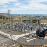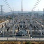

Imagine a large metropolitan city where millions of homes, factories, hospitals, airports, and data centers depend on a continuous electricity supply every second. Electricity generated hundreds of kilometers away must travel across the country without significant power loss. This is possible because of high-voltage transmission systems and 400kV Grid Stations, which act as major control centers in the national power grid. Without these grid stations, transmitting huge amounts of electrical power safely and efficiently over long distances would be extremely difficult.
Understanding the 400kV Grid Station Working Principle is essential for electrical engineering students, technicians, and practicing engineers because these substations form the backbone of modern transmission networks. They ensure reliable power delivery, protect expensive equipment from faults, and maintain voltage stability across the electrical grid.
In this comprehensive guide, you will learn what a 400kV Grid Station is, how it works step by step, its major components, different types, advantages and disadvantages, practical applications, comparisons with other voltage levels, troubleshooting tips, selection guidelines, and future developments. The explanations are written in simple English while maintaining professional engineering accuracy, making the topic easy to understand for both beginners and experienced professionals.
What is a 400kV Grid Station?
A 400kV Grid Station is an extra-high-voltage (EHV) electrical substation that receives, controls, protects, and distributes electrical power at 400 kilovolts (400,000 volts). It is one of the most important parts of the transmission system because it transfers large amounts of electrical energy over long distances with minimum transmission losses.
The main purpose of a 400kV Grid Station is to receive electricity from generating stations or other transmission substations, manage the power flow, and reduce the voltage to lower transmission levels such as 220kV, 132kV, or 66kV before further distribution.
Simple Explanation
Think of a 400kV Grid Station as a giant highway interchange.
- Power plants are the starting points.
- Transmission lines are the highways.
- Electricity is the traffic.
- The grid station controls where the electricity goes and how it reaches different destinations safely.
Practical Example
A hydroelectric power plant generates electricity that is transmitted through 400kV transmission lines. When the electricity reaches a nearby 400kV Grid Station, the station routes some power to another transmission line while reducing the remaining voltage to 220kV for regional transmission and eventually to lower voltages for consumers.
Working Principle
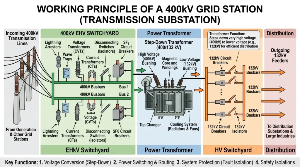
The 400kV Grid Station Working Principle is based on receiving high-voltage electrical energy, protecting the transmission network, controlling power flow, transforming voltage levels, and delivering electricity safely to different parts of the grid.
The entire process follows a carefully designed sequence.
Receiving High-Voltage Power
Electrical energy generated by power stations enters the grid station through incoming 400kV transmission lines.
These lines carry massive amounts of electrical power over long distances.
Lightning and Surge Protection
Before entering the main equipment, lightning arresters protect the station against lightning strikes and switching surges.
This prevents damage to transformers, circuit breakers, and other expensive equipment.
Isolation of Equipment
Isolators (disconnect switches) are used to safely disconnect equipment during maintenance.
They provide visible isolation but are operated only when there is no load current.
Measurement and Monitoring
Instrument transformers continuously measure:
- Voltage
- Current
- Frequency
- Power flow
The measured values are sent to meters, protection relays, and control systems.
Fault Detection
Protective relays constantly monitor the electrical system.
If any abnormal condition is detected, such as:
- Short circuit
- Earth fault
- Overcurrent
- Differential fault
the relay immediately sends a trip signal.
Circuit Breaker Operation
The circuit breaker receives the trip signal and disconnects the faulty section within milliseconds.
This protects the remaining network from damage.
Voltage Transformation
Large power transformers reduce the voltage according to system requirements.
Examples include:
- 400kV → 220kV
- 400kV → 132kV
Lower transmission voltages are then supplied to regional substations.
Outgoing Transmission
The processed electrical power leaves the grid station through outgoing transmission feeders and continues toward cities, industries, and distribution substations.
Easy Analogy
Imagine an international airport.
- Incoming flights represent transmission lines.
- Air traffic control represents the control room.
- Security systems represent protection relays.
- Gates represent outgoing feeders.
- Aircraft changing terminals represent transformers changing voltage levels.
Everything is coordinated to keep the system safe, organized, and efficient.
Types / Classification
Although the 400kV Grid Station Working Principle remains the same, grid stations are classified according to insulation method and installation type.
Air Insulated Substation (AIS)
Air serves as the insulation medium between live equipment.
Features
- Lower construction cost
- Easy maintenance
- Large installation area
- Widely used worldwide
Applications
- National transmission systems
- Rural transmission stations
- Utility power networks
Gas Insulated Substation (GIS)
GIS uses sulfur hexafluoride (SF₆) gas inside sealed metal enclosures.
Features
- Compact design
- Excellent reliability
- High insulation strength
- Minimal exposure to weather
Applications
- Urban areas
- Underground substations
- Coastal regions
- Industrial facilities
Indoor Grid Station
Electrical equipment is installed inside specially designed buildings.
Features
- Better environmental protection
- Increased safety
- Reduced weather-related failures
Outdoor Grid Station
Most 400kV substations are outdoor installations.
Features
- Lower installation cost
- Easy expansion
- Convenient equipment access
Main Components
Every 400kV Grid Station consists of several important components.
Power Transformer
Function
- Steps voltage down
- Transfers electrical power efficiently
- Provides electrical isolation
Circuit Breaker
Function
- Interrupts fault current
- Protects transmission equipment
- Performs switching operations
Isolator
Function
- Disconnects equipment safely
- Allows maintenance work
- Provides visible electrical isolation
Busbar
Function
- Collects incoming electrical power
- Distributes electricity to multiple outgoing circuits
Current Transformer (CT)
Function
- Measures high current safely
- Supplies protection relays
- Supports energy metering
Capacitive Voltage Transformer (CVT)
Function
- Measures high voltage
- Provides voltage signals for protection
- Supports carrier communication
Lightning Arrester
Function
- Protects against lightning surges
- Limits transient overvoltages
Protective Relays
Function
- Detect electrical faults
- Control circuit breaker operation
- Improve system reliability
Control and Relay Panels
Function
- Monitor the complete station
- Display alarms
- Operate switching equipment
Earthing System
Function
- Protect personnel
- Safely discharge fault current
- Improve operational safety
Advantages
Understanding the 400kV Grid Station advantages and disadvantages helps explain why these substations are widely used in transmission systems.
Advantages
- Efficient long-distance power transmission
- Very low transmission losses
- High power transfer capability
- Excellent system reliability
- Supports national electrical grids
- Provides strong fault protection
- Improves voltage stability
- Enables easy expansion of transmission networks
- Reduces overall operating costs
- Supports renewable energy integration
Real-World Benefits
- Reliable electricity supply for major cities.
- Stable power for industries and infrastructure.
- Reduced energy wastage during transmission.
- Improved electrical network stability.
Disadvantages / Limitations
Despite many advantages, there are some practical limitations.
- High installation cost
- Expensive equipment
- Requires highly skilled operators
- Large land requirement for AIS
- Regular maintenance is essential
- Protection systems are complex
- Construction takes considerable time
- Environmental clearance may be required
Applications
The 400kV Grid Station applications are essential in modern electrical infrastructure.
National Transmission Networks
- Interconnecting power plants
- Long-distance electricity transmission
- National grid stability
Industrial Applications
- Steel industries
- Oil refineries
- Chemical plants
- Heavy manufacturing
Commercial Infrastructure
- Airports
- Metro rail systems
- Data centers
- Smart cities
Renewable Energy
- Large solar parks
- Wind farms
- Hydroelectric stations
- Hybrid renewable projects
Emergency Power Transfer
- Load balancing
- Grid restoration
- Inter-regional power exchange
Comparison Section
Many students ask about the difference between 400kV Grid Station and 220kV Grid Station.
| Feature | 400kV Grid Station | 220kV Grid Station |
| Operating Voltage | 400kV | 220kV |
| Power Transfer | Very High | High |
| Transmission Distance | Longer | Medium |
| Installation Cost | Higher | Lower |
| Equipment Rating | Larger | Moderate |
| Main Purpose | National transmission | Regional transmission |
Another useful comparison is shown below.
| Feature | 400kV Grid Station | Distribution Substation |
| Voltage Level | Extra High Voltage | Medium or Low Voltage |
| Coverage Area | National and regional | Local consumers |
| Equipment Size | Very Large | Smaller |
| Main Function | Transmission control | Power distribution |
Selection Guide
Selecting a suitable 400kV Grid Station depends on several engineering considerations.
Expected Load
Estimate present and future electrical demand carefully.
Transformer Capacity
Select transformers with sufficient capacity and future expansion capability.
Site Conditions
Choose locations considering:
- Soil strength
- Flood protection
- Accessibility
- Environmental impact
Protection Requirements
Modern substations should include:
- Numerical relays
- Redundant protection
- Fast fault clearing
Expansion Capability
Provide space for:
- Additional transformers
- Future feeders
- Busbar extensions
Safety Standards
Ensure compliance with national electrical codes and utility standards.
Tips for Beginners
- Learn single-line diagrams before studying equipment.
- Understand the function of each component individually.
- Study protection schemes carefully.
- Never overlook earthing and safety practices.
- Observe actual substations whenever possible to connect theory with practice.
Common Problems & Solutions
Why does the circuit breaker trip repeatedly?
Causes
- Short circuit
- Overload
- Relay malfunction
Solution
Inspect the feeder, verify relay settings, and locate the fault before restoring service.
Why is transformer temperature high?
Causes
- Excessive loading
- Cooling fan failure
- Low transformer oil
Solution
Reduce loading and inspect the cooling system immediately.
Why is busbar voltage fluctuating?
Causes
- Network instability
- Transformer issue
- Sudden load changes
Solution
Check transformer operation and monitor incoming transmission lines.
Why are protection relays giving false alarms?
Causes
- Incorrect settings
- Faulty CT or CVT
- Wiring problems
Solution
Test the protection system and recalibrate settings where necessary.
Why is earthing so important?
A proper earthing system protects personnel, limits dangerous touch voltages, and safely carries fault currents away from equipment.
Future Trends
Modern transmission systems are rapidly becoming more intelligent.
Future 400kV Grid Station Working Principle improvements include:
- Fully digital substations
- IEC 61850-based communication
- Smart sensors
- Artificial intelligence for predictive maintenance
- Condition-based monitoring
- IoT-enabled equipment
- Remote operation and diagnostics
- Advanced cybersecurity
- Eco-friendly insulation technologies
- Greater integration with renewable energy and smart grids
These innovations will make future substations more reliable, safer, and easier to operate while reducing maintenance costs and improving overall grid performance.
Conclusion
Understanding the 400kV Grid Station Working Principle is essential for anyone pursuing a career in electrical engineering or power systems. These extra-high-voltage substations play a critical role in receiving, protecting, controlling, transforming, and transmitting electrical power across vast distances with high efficiency. Their advanced equipment, including transformers, circuit breakers, protective relays, and control systems, ensures reliable electricity delivery while maintaining grid stability and safety. By learning about the working principle, components, classifications, applications, advantages, limitations, and future developments of 400kV Grid Stations, students and professionals gain the knowledge needed to understand modern transmission networks. A strong foundation in these concepts will help you confidently analyze, operate, and maintain high-voltage power systems throughout your engineering career.