
Power system engineers routinely work with voltages from 400 V to 765 kV and currents of thousands of amperes. Doing calculations directly in volts, amps, and ohms across transformers is messy — every transformer crossing forces all values to be referred from one side to the other. The per unit system eliminates this headache by expressing every quantity as a fraction of a chosen base value.
What Is the Per Unit System?
The per unit (pu) system is a method of expressing electrical quantities — voltage, current, impedance, and power — as dimensionless ratios of their actual values to selected base values:
Per unit value = Actual value / Base value
For example, if the base voltage is 132 kV and the actual voltage is 126 kV, the per-unit voltage is 126/132 = 0.9545 pu. Instead of juggling kilovolts on one side of a transformer and volts on the other, engineers work with small, comparable numbers typically near 1.0 pu.
The per unit system is the standard language of power system analysis — load flow studies, short-circuit calculations, stability analysis, and protective relaying settings are all done in per unit.
Choosing Base Values
You are free to choose base values, but two are selected independently and the rest are derived:
- Base power (S_base): Usually the system MVA rating, e.g. 100 MVA. One base MVA is used for the entire network.
- Base voltage (V_base): Usually the nominal line-to-line voltage of each voltage zone, e.g. 132 kV on the HV side and 33 kV on the LV side.
From these, all other base quantities follow:
- Base current: I_base = S_base / (√3 × V_base)
- Base impedance: Z_base = V_base² / S_base
Because the base voltage changes at each transformer (following the turns ratio) while base MVA stays constant, a transformer with a 1:1 per-unit turns ratio effectively disappears from per-unit calculations — no more referring impedances across windings.
Per Unit Formulas
For any quantity, divide the actual (ohmic) value by the base value in consistent units:
- Voltage: V_pu = V_actual / V_base
- Current: I_pu = I_actual / I_base
- Impedance: Z_pu = Z_actual / Z_base = Z_ohms × S_base / V_base²
- Power: S_pu = S_actual / S_base (and similarly P_pu = P / S_base, Q_pu = Q / S_base)
A handy shortcut for impedance: with S_base in MVA and V_base in kV, Z_base = V_base² / S_base gives ohms directly. So a 10 Ω reactance on a 132 kV, 100 MVA base is Z_pu = 10 × 100 / 132² = 1000 / 17424 = 0.0574 pu.
Why the Per Unit System Is Used: Key Advantages
- Transformer simplification: Ideal transformers vanish in per-unit; impedances need no referring across voltage levels.
- Comparable magnitudes: Generator subtransient reactances, line impedances, and transformer impedances all land in the convenient 0.01–1.0 pu range, making errors easier to spot.
- Fewer calculation errors: Working with small dimensionless numbers reduces mistakes with unit conversions and √3 factors.
- Equipment data compatibility: Manufacturers quote transformer and machine impedances in percent or per unit on the equipment’s own ratings — easily converted to a common system base.
- Universal language: Studies, relay settings, and software (load flow, short circuit) all operate in per unit.
Converting Impedance Between Bases
Manufacturer data is given on the equipment’s own MVA and voltage ratings, which usually differ from the system base. The conversion formula is:
Z_pu(new) = Z_pu(old) × (S_base_new / S_base_old) × (V_base_old / V_base_new)²
This single formula is one of the most-used equations in power system practice. Example: a transformer rated 50 MVA, 132/33 kV has a nameplate impedance of 8% (0.08 pu on its own base). On a 100 MVA system base with the same voltages:
Z_pu = 0.08 × (100 / 50) × (132 / 132)² = 0.08 × 2 = 0.16 pu
Notice the impedance in per unit doubled when the base MVA doubled — a useful sanity check, since Z_pu scales directly with S_base.
Worked Example 1: Simple Per Unit Calculation
A 33 kV feeder supplies a 5 MVA load. The feeder impedance is 2 + j6 Ω per phase. Use S_base = 10 MVA and V_base = 33 kV.
- Z_base = V_base² / S_base = 33² / 10 = 1089 / 10 = 108.9 Ω
- Z_pu = (2 + j6) / 108.9 = 0.0184 + j0.0551 pu
- Load in per unit: S_pu = 5 / 10 = 0.5 pu
If the load operates at 0.9 power factor lagging, P_pu = 0.45 pu and Q_pu = 0.218 pu. Everything is now a tidy number near or below 1.0.
Worked Example 2: Transformer on System Base
A generator rated 20 MVA, 11 kV has a subtransient reactance of 15% (0.15 pu on its own rating). Convert to a 100 MVA system base at 11 kV.
Z_pu(new) = 0.15 × (100 / 20) × (11 / 11)² = 0.15 × 5 = 0.75 pu
The generator’s reactance is 0.75 pu on the system base — ready to drop into a fault-level calculation alongside line and transformer impedances on the same 100 MVA base.
Worked Example 3: Short-Circuit Current Using Per Unit
A 100 MVA, 132/33 kV transformer has 10% impedance. It feeds a 33 kV bus. A three-phase fault occurs on the 33 kV bus. Assuming an infinite source behind the transformer, find the fault current.
- Convert transformer impedance: Z_pu = 0.10 pu on 100 MVA (already on system base).
- Fault MVA = Base MVA / Z_pu = 100 / 0.10 = 1000 MVA
- Base current at 33 kV: I_base = 100,000 / (√3 × 33) = 100,000 / 57.16 = 1749.5 A
- Fault current = 1000 MVA / (√3 × 33 kV) = 1,000,000 / 57.16 ≈ 17,495 A ≈ 17.5 kA
Equivalently, I_fault_pu = V_pu / Z_pu = 1.0 / 0.10 = 10 pu, and 10 × 1749.5 A = 17.5 kA. This is exactly how protection engineers size circuit breakers and set overcurrent relays.
Per Unit vs Percent Values
Percent values are simply per-unit values × 100. A transformer impedance of 0.08 pu is quoted as 8%. Percent is common on nameplates and in conversation; per unit is preferred in calculations because it avoids constant factors of 100. Converting is trivial, but be consistent within a single study — mixing percent and per unit in one equation is a classic source of errors.
Common Mistakes to Avoid
- Forgetting the voltage-squared term in the base-change formula — the most frequent error.
- Using line-to-neutral voltage where line-to-line is required (or vice versa) when computing Z_base.
- Mixing single-phase and three-phase bases: for three-phase work, S_base is three-phase MVA and V_base is line-to-line kV.
- Skipping the base change and using nameplate per-unit impedance directly on the system base.
Applications in Power Systems
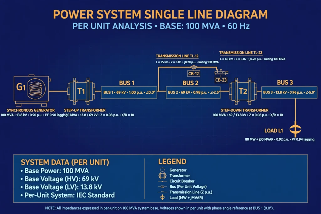
The per unit system underpins nearly every power system study: load flow analysis, symmetrical and unsymmetrical fault calculations, transient stability simulations, motor starting studies, protective relay coordination, and transformer paralleling checks. Any time you see single-line diagrams annotated with values like “j0.12” or “0.95 pu,” you are looking at per-unit analysis in action. For real-world context, see our guides to electrical power plant, types of electrical substations, and electrical impedance.
Frequently Asked Questions
What is the per unit system in power systems?
It is a normalization method where voltages, currents, impedances, and powers are expressed as ratios of their actual values to chosen base values, producing dimensionless numbers (usually near 1.0) that simplify analysis across transformers.
What are the base values in the per unit system?
Base MVA (S_base, common to the whole system) and base voltage (V_base, the nominal voltage of each voltage zone). Base current and base impedance are derived: I_base = S_base/(√3·V_base), Z_base = V_base²/S_base.
What is the formula for per unit impedance?
Z_pu = Z_actual / Z_base = Z_ohms × S_base / V_base². To change bases: Z_pu(new) = Z_pu(old) × (S_new/S_old) × (V_old/V_new)².
Why is the per unit system preferred over actual values?
It eliminates transformer turns-ratio conversions, keeps all quantities in a convenient numerical range, reduces unit-conversion errors, and matches how manufacturers quote equipment data and how analysis software works.
What is the difference between per unit and percent impedance?
Percent impedance = per unit impedance × 100. They carry identical information; per unit is used in calculations, percent on nameplates and in discussion.
Can per unit values exceed 1.0?
Yes. Voltages are usually near 1.0 pu, but fault currents are often many per unit (e.g. 10 pu), and impedances of small equipment on a large system base can exceed 1.0 pu. It is just a ratio, not a limit. For more background, see Wikipedia.
Conclusion
The per unit system turns the sprawling, multi-voltage reality of a power network into clean, comparable numbers. Choose a system MVA base and nominal voltages, derive the remaining bases, convert all equipment impedances with the base-change formula, and the transformers effectively disappear from your calculations. Master these few formulas — V_pu, I_pu, Z_pu, and the base conversion — and you have the working language of load flow, fault analysis, and protection engineering. It is a small upfront investment that pays off in every power system calculation you will ever do.