
Every unit of electricity you use has passed through several substations on its journey from the power plant to your socket. These fenced compounds full of transformers, breakers and busbars are the junctions of the power grid — stepping voltage up for efficient long-distance travel, then stepping it down again for safe local use.
If you are new to the subject, start with our overview of what an electrical substation is and why the grid needs it. This guide goes further: it classifies substations by voltage level, by function and by physical design, and walks through the key components you will find inside each type.
Classification by Voltage Level
The most common way engineers talk about substations is by the voltage they handle. Higher voltage means bulk power over long distances; lower voltage means power close to the consumer.
| Category | Typical voltage range | Role in the grid |
|---|---|---|
| Distribution substation | 11 kV / 400 V (or 33/11 kV) | Final step-down feeding homes, shops and small industry |
| Sub-transmission substation | 33 kV – 66 kV | Feeds distribution networks and medium industries |
| Transmission substation | 132 kV – 220 kV | Bulk transfer between regions and large load centers |
| Extra-high-voltage (EHV) substation | 400 kV – 765 kV and above | Interstate and inter-regional backbone of the grid |
Real examples help: a 132 kV grid station is a transmission-level substation, while a 33 kV grid station typically serves sub-transmission duty. If the terminology of “grid station” versus “substation” confuses you, our grid station vs substation comparison sorts it out.
Classification by Function
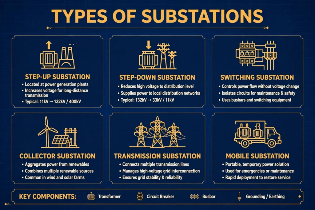
1. Step-up (generating) substation: located at the power plant, it raises generator voltage (typically 11–20 kV) to transmission voltage (132 kV and above) so power can travel hundreds of kilometers with low losses.
2. Step-down (primary) substation: at the receiving end of transmission lines, it reduces EHV to sub-transmission levels such as 132 kV or 66 kV.
3. Distribution substation: the last transformation stage, dropping 11 kV or 33 kV to 400/230 V for consumers. These are the pole-mounted or compact units you see in streets and housing societies.
4. Switching substation: contains no power transformer at all — it only switches, routes and protects lines. It lets grid operators reconfigure the network during faults or maintenance.
5. Converter substation: found on HVDC links, converting AC to DC for long-distance or submarine transmission and back to AC at the other end.
6. Industrial substation: a private substation inside a factory or mine, stepping utility supply down to the plant’s utilization voltages and often including power-factor correction equipment.
Classification by Design and Installation
1. Outdoor (open-air) substation: the classic fenced yard with equipment mounted on steel structures in the open. Cheapest to build but needs large land area and suffers weather exposure.
2. Indoor substation: all equipment housed inside a building. Used in cities where land is scarce or pollution is heavy, for voltages up to about 66 kV.
3. Air-insulated switchgear (AIS): uses open air as the main insulation between live parts. Needs generous clearances, so the footprint is large.
4. Gas-insulated switchgear (GIS): live parts sealed in metal enclosures filled with SF6 gas. The footprint shrinks to a tenth of AIS, making GIS the choice for dense urban sites — at a much higher price.
5. Pole-mounted substation: a small distribution transformer and fuses mounted on a pole. The workhorse of rural electrification.
6. Mobile substation: a complete substation on trailers, rolled in for emergencies, planned maintenance outages or temporary loads like construction sites.
Key Components Found in a Substation
Whatever the type, most substations share the same family of equipment:
- Power transformer: the heart of the substation, changing voltage from one level to another.
- Busbar: the copper or aluminium bars that collect and distribute power to outgoing feeders. See our guide to the busbar system for layouts like single, double and ring bus.
- Circuit breaker: interrupts fault current in milliseconds to protect equipment and people.
- Isolator (disconnector): provides a visible break for maintenance — it never opens under load.
- Current and voltage transformers (CT/VT): step high currents and voltages down to measurable levels for meters and protection relays.
- Lightning arrester: diverts lightning surges safely to earth before they can puncture insulation.
- Earthing system: every metallic structure is bonded to an earth grid for safety and fault-current return.
- Control and relay panels: the substation’s brain — protection relays, meters and SCADA interfaces live here.
The coordinated operation of breakers, relays and instrument transformers is what engineers call switchgear, and it deserves study on its own.
How to Read a Substation Single-Line Diagram
Engineers describe substations with single-line diagrams: one line represents all three phases, and standard symbols stand for breakers, isolators, transformers and busbars. Learning to trace power flow on these drawings — from incoming line, through the breaker and CT, across the busbar, out through the feeder breaker to the transformer — is the fastest way to understand any substation layout. Start with a simple single-bus scheme, then graduate to double-bus and breaker-and-a-half arrangements used at transmission level.
FAQs
What is the difference between a substation and a grid station?
In everyday use the terms overlap heavily. Strictly, a grid station is a substation connected to the transmission grid at high voltage, while “substation” covers every voltage level down to distribution. Our detailed comparison explains the difference between grid station and substation.
Why are some substations so large?
Size follows voltage: higher voltage needs larger clearances between live parts and earth for insulation, so EHV substations sprawl over acres while a distribution substation fits on a pole or a small plinth.
What is GIS vs AIS in substations?
AIS (air-insulated switchgear) uses open air as insulation and needs lots of space; GIS (gas-insulated switchgear) seals equipment in SF6-filled enclosures, shrinking the footprint dramatically at higher cost.
Do all substations have transformers?
No. Switching substations contain only breakers, isolators and busbars for routing power, with no voltage transformation at all.
Why are substations fenced and locked?
Because exposed high-voltage equipment can kill on contact or even by close approach (flashover). Fencing, warning signs and interlocked gates keep the public and animals at a safe distance.
How often is substation equipment maintained?
Transformers and breakers follow strict schedules — oil testing, contact checks, protection relay testing — typically annually, with continuous online monitoring at important transmission substations.
Conclusion
Substations come in many types, but the classification logic is simple: voltage level tells you where it sits in the grid, function tells you what it does to the power, and design tells you how it is built for its site. Learn to recognize a step-up transmission yard versus a pole-mounted distribution unit, know the job of each component inside, and the power system stops being a mystery of humming fences and becomes an organized, readable machine.
Further reading: Electrical substation — Wikipedia.