
Imagine charging your smartphone, powering your laptop, or using an LED television. Although your home receives Alternating Current (AC) from the electrical grid, these electronic devices operate using Direct Current (DC). The device responsible for converting AC into DC is called a Rectifier Circuit. Without it, most modern electronic equipment would not work.
A Rectifier Circuit is one of the fundamental building blocks of electrical and electronic engineering. It is used in almost every power supply, battery charger, industrial controller, and electronic appliance. Whether you are designing a simple electronics project or working with industrial power systems, understanding rectifier circuits is essential.
Learning the Rectifier Circuit working principle helps students, engineers, technicians, and beginners understand how electrical energy is converted into a usable form for electronic devices. It also builds a strong foundation for studying power electronics, power supplies, and electrical machines.
In this comprehensive guide, you will learn what a Rectifier Circuit is, how it works, its types, major components, advantages, disadvantages, applications, comparison with inverter circuits, selection tips, troubleshooting methods, and future developments in rectifier technology.
What is a Rectifier Circuit?
A Rectifier Circuit is an electrical or electronic circuit that converts Alternating Current (AC) into Direct Current (DC) using semiconductor devices, usually diodes.
Since AC changes its direction periodically while DC flows in only one direction, a rectifier circuit allows current to flow in one direction and blocks it in the opposite direction.
Simple Explanation
Think of a one-way road where vehicles are allowed to move only in one direction. A diode inside a rectifier circuit behaves in a similar way. It allows electric current to pass in one direction while preventing reverse current flow.
Practical Example
A mobile phone charger contains a rectifier circuit. It receives 230V AC from the wall outlet and converts it into DC voltage before further regulating it to safely charge your phone’s battery.
Rectifier Circuit Working Principle
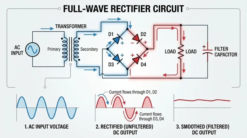
The Rectifier Circuit working principle is based on the one-way conduction property of semiconductor diodes. A diode conducts current only when it is forward biased and blocks current when reverse biased.
By arranging one or more diodes in specific configurations, alternating current is converted into pulsating direct current.
Step-by-Step Working Principle
AC Input Supply
The rectifier receives AC voltage from an electrical source.
Typical sources include:
- Household mains
- Transformer secondary winding
- Generator output
Positive Half Cycle
During the positive half cycle:
- The diode becomes forward biased.
- Current flows through the load.
- The output voltage appears across the load.
Negative Half Cycle
Depending on the rectifier type:
- The diode blocks current (half-wave rectifier), or
- Another diode conducts (full-wave and bridge rectifiers).
This ensures current always flows through the load in the same direction.
Pulsating DC Output
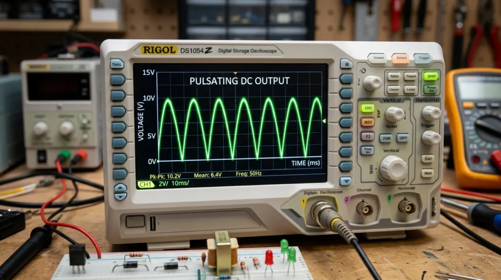
Pulsating DC output is a type of direct current produced by a rectifier in which the current flows in only one direction, but its voltage continuously rises and falls instead of remaining constant. Unlike pure DC, which has a steady voltage level, pulsating DC contains ripples because it is directly converted from alternating current (AC). The amount of ripple depends on the type of rectifier used, with half-wave rectifiers producing more ripple than full-wave or bridge rectifiers. In many electronic circuits, filters such as capacitors or voltage regulators are added to smooth the pulsating DC into a more stable and reliable DC supply. Pulsating DC is commonly found in basic power supply circuits, battery chargers, and electronic devices before the filtering stage.
The rectifier converts AC into pulsating DC.
Although the current now flows in only one direction, the voltage still contains ripples.
Filtering
A capacitor or LC filter smooths the pulsating DC by reducing voltage ripple.
This provides a steadier DC output.
Voltage Regulation
Many power supplies include a voltage regulator after the rectifier to maintain a constant output voltage despite changes in input voltage or load.
Easy Analogy
Imagine filling a bucket with water using waves from the sea. The incoming water rises and falls, just like AC voltage. A storage tank connected to the bucket smooths these fluctuations, giving you a more constant water supply. Similarly, a filter capacitor smooths the pulsating DC produced by a rectifier.
Types of Rectifier Circuit
Different applications require different rectifier configurations.
Half-Wave Rectifier
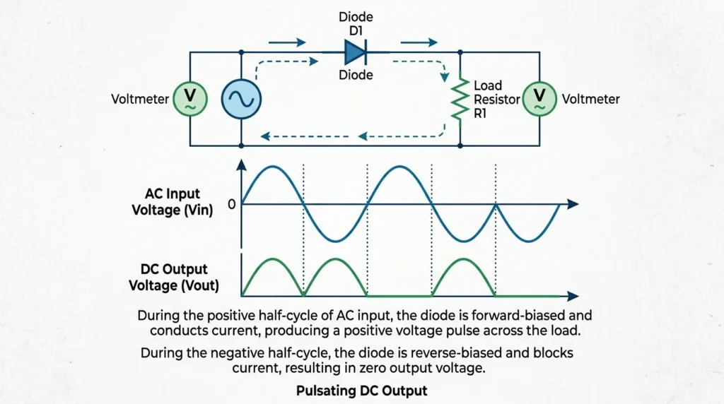
A half-wave rectifier is an electronic circuit that converts alternating current (AC) into pulsating direct current (DC) by allowing only one half-cycle of the AC input to pass through while blocking the other half. It typically uses a single diode as the main rectifying component. During the positive half-cycle, the diode conducts and current flows through the load, producing a positive output. During the negative half-cycle, the diode becomes reverse-biased and blocks the current, resulting in no output. Because it utilizes only half of the input waveform, a half-wave rectifier has low efficiency and produces a high ripple content compared to a full-wave rectifier. It is commonly used in low-power applications such as signal detection, battery chargers, and simple DC power supplies where high-quality DC output is not required.A half-wave rectifier uses a single diode and converts only one half of the AC waveform into DC.
Features
- Simple circuit
- Low cost
- High ripple
- Low efficiency
Applications
- Educational experiments
- Low-power electronic circuits
- Signal detection
Full-Wave Rectifier (Center-Tapped)
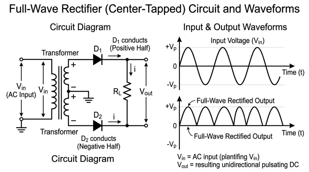
A full-wave rectifier (center-tapped) is an electronic circuit that converts both the positive and negative half-cycles of an alternating current (AC) input into pulsating direct current (DC). It uses a center-tapped transformer and two diodes to achieve full-wave rectification. During the positive half-cycle, one diode conducts while the other remains reverse-biased. During the negative half-cycle, the second diode conducts, allowing current to flow through the load in the same direction. As a result, both halves of the AC waveform are utilized, producing a higher average DC output with lower ripple than a half-wave rectifier. Although it requires a center-tapped transformer, this rectifier offers better efficiency, improved transformer utilization, and smoother DC output, making it suitable for DC power supplies, battery chargers, and low- to medium-power electronic circuits.
This rectifier uses two diodes and a center-tapped transformer.
Features
- Uses both half cycles
- Higher efficiency than half-wave rectifier
- Lower ripple
- Better output quality
Applications
- Medium-power supplies
- Laboratory equipment
- Analog electronics
Bridge Rectifier
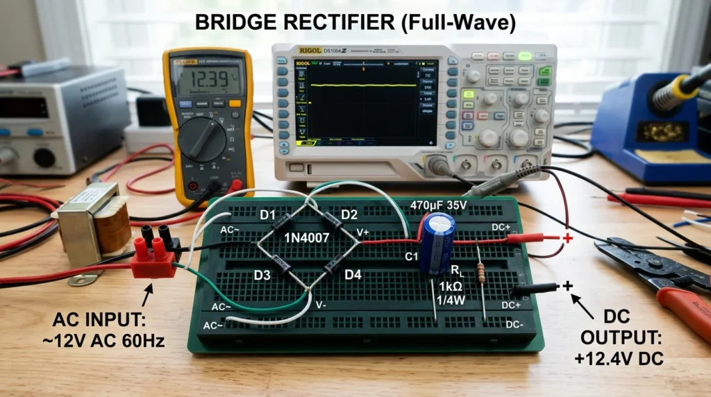
A bridge rectifier is an electronic circuit that converts alternating current (AC) into pulsating direct current (DC) by using four diodes connected in a bridge configuration. Unlike a center-tapped full-wave rectifier, it does not require a center-tapped transformer, making it more economical and widely used. During the positive half-cycle of the AC input, two diodes conduct, while during the negative half-cycle, the other two diodes conduct, ensuring that current always flows through the load in the same direction. This allows the bridge rectifier to utilize both halves of the AC waveform, resulting in a higher average DC output, better efficiency, and lower ripple compared to a half-wave rectifier. Due to its simple design, reliable performance, and efficient power conversion, bridge rectifiers are commonly used in power supplies, battery chargers, household electronics, industrial equipment, and electronic devices.A bridge rectifier uses four diodes connected in a bridge configuration.
Features
- No center-tapped transformer required
- High efficiency
- Compact design
- Most widely used rectifier
Applications
- Mobile chargers
- Laptop adapters
- Television power supplies
- Industrial equipment
Controlled Rectifier
Controlled rectifiers replace standard diodes with thyristors or SCRs (Silicon Controlled Rectifiers).
Features
- Adjustable output voltage
- Controlled switching
- High power capability
Applications
- Motor speed control
- Industrial power supplies
- Battery charging systems
Main Components
A Rectifier Circuit consists of several components working together to produce stable DC power.
Transformer
Function:
- Steps up or steps down AC voltage
- Provides electrical isolation
- Matches the required output voltage
Diodes
Function:
- Convert AC into DC
- Allow current in one direction
- Block reverse current
Filter Capacitor
Function:
- Smooths pulsating DC
- Reduces ripple voltage
- Improves output quality
Inductor (Optional)
Function:
- Reduces current ripple
- Improves filtering in high-power circuits
Voltage Regulator
Function:
- Maintains constant DC voltage
- Protects connected devices
Load
Function:
- Consumes the DC power supplied by the rectifier
- Can be an electronic circuit, battery, or motor controller
Fuse
Function:
- Protects the circuit from overcurrent
- Prevents damage during faults
Rectifier Circuit Advantages
Understanding the Rectifier Circuit advantages and disadvantages helps users choose the right design for different applications.
Advantages
- Converts AC into usable DC power
- Simple and reliable operation
- Low maintenance requirements
- High efficiency, especially in full-wave and bridge rectifiers
- Suitable for a wide range of voltage levels
- Widely available and cost-effective
- Supports battery charging
- Essential for electronic power supplies
- Long service life
- Easy to integrate with filters and voltage regulators
- Supports both low-power and high-power applications
- Reliable performance under continuous operation
Rectifier Circuit Disadvantages / Limitations
Although rectifier circuits are highly useful, they have some limitations.
- Output contains ripple without filtering.
- Diodes introduce a forward voltage drop.
- Half-wave rectifiers have poor efficiency.
- Heat generation increases at higher power levels.
- Large filter capacitors may be required.
- Controlled rectifiers require more complex control circuits.
- Harmonics may affect the AC supply in high-power applications.
- Cooling may be necessary for heavy loads.
Rectifier Circuit Applications
The wide range of Rectifier Circuit applications makes them indispensable in modern electrical and electronic systems.
Home Applications
- Mobile phone chargers
- Laptop adapters
- LED televisions
- LED lighting
- Home audio systems
Industrial Applications
- DC motor drives
- Industrial automation
- Welding equipment
- Electroplating
- Battery charging stations
- Variable speed drives
Commercial Applications
- Office electronics
- UPS systems
- Network equipment
- Security systems
Renewable Energy
- Solar charge controllers
- Wind power systems
- Battery energy storage
- Hybrid power systems
Medical Applications
- Medical diagnostic equipment
- Laboratory instruments
- Patient monitoring devices
Modern Technology
- Electric vehicle chargers
- Robotics
- Data centers
- Telecommunication systems
- Consumer electronics
- Smart appliances
Comparison: Rectifier Circuit vs Inverter Circuit
Understanding the difference between Rectifier Circuit and Inverter Circuit helps beginners distinguish these two important power electronic circuits.
| Feature | Rectifier Circuit | Inverter Circuit |
| Input | Alternating Current (AC) | Direct Current (DC) |
| Output | Direct Current (DC) | Alternating Current (AC) |
| Main Function | Converts AC to DC | Converts DC to AC |
| Main Components | Diodes or SCRs | Transistors, MOSFETs, or IGBTs |
| Common Applications | Power supplies, chargers | UPS systems, solar inverters |
| Direction of Conversion | AC → DC | DC → AC |
Selection Guide
Selecting the correct Rectifier Circuit depends on the application and electrical requirements.
Determine the Output Voltage
Choose a rectifier that provides the required DC voltage for the load.
Consider Load Current
Ensure the rectifier can safely handle the expected current with an additional safety margin.
Select the Appropriate Type
- Half-wave for simple, low-power circuits
- Full-wave for better performance
- Bridge rectifier for most general-purpose applications
- Controlled rectifier for adjustable DC output
Check Ripple Requirements
If the application requires clean DC, choose a rectifier with adequate filtering and voltage regulation.
Evaluate Thermal Performance
For high-power applications:
- Use heat sinks
- Ensure proper ventilation
- Select components with suitable power ratings
Verify Safety Features
Choose designs with:
- Overcurrent protection
- Fuses
- Surge protection
- Proper insulation
Common Problems & Solutions
Why is there no DC output?
causes:
- Blown fuse
- Faulty diode
- Loose wiring
Solution:
Check input power, inspect the diodes, and replace damaged components.
Why is the output voltage too low?
causes:
- Defective transformer
- Overloaded circuit
- Worn filter capacitor
Solution:
Reduce the load and test the transformer and capacitor.
Why is the output very noisy?
causes:
- Failed filter capacitor
- Poor grounding
- Loose electrical connections
Solution:
Replace faulty capacitors and improve grounding.
Why are the diodes overheating?
causes:
- Excessive load current
- Inadequate heat sinking
- Short circuit
Solution:
Check the load, improve cooling, and inspect the circuit for faults.
Why is the fuse blowing repeatedly?
causes:
- Shorted diode
- Internal short circuit
- Excessive input current
Solution:
Test each diode, inspect wiring, and replace damaged components before installing a new fuse.
Future Trends
Rectifier technology continues to improve with advances in semiconductor devices and power electronics.
Future developments include:
- Silicon Carbide (SiC) rectifiers for higher efficiency
- Gallium Nitride (GaN) power devices for faster switching
- Smart digital power supplies
- Compact high-density rectifier modules
- Improved thermal management systems
- Lower electromagnetic interference designs
- Integration with renewable energy systems
- High-efficiency electric vehicle charging technology
- Intelligent monitoring and fault diagnostics
- More environmentally friendly and energy-efficient designs
These advancements will provide better performance, higher reliability, and lower energy losses across industrial and consumer applications.
Conclusion
A Rectifier Circuit is one of the most important building blocks in electrical and electronic engineering because it converts alternating current into direct current for powering modern devices. Understanding the Rectifier Circuit working principle helps students, technicians, and engineers build a strong foundation in power electronics and electrical power supplies. From simple half-wave rectifiers to advanced bridge and controlled rectifiers, each type serves specific applications based on efficiency, cost, and performance requirements. Although rectifier circuits have limitations such as ripple voltage and heat generation, proper filtering, voltage regulation, and thermal management can overcome these challenges. As semiconductor technology continues to advance, rectifier circuits will become even more efficient, compact, and reliable, supporting the growing demand for energy-efficient electronic devices, industrial automation, renewable energy systems, and electric transportation.