
Imagine managing a factory where several large electric motors run all day. At the end of the month, you notice that the electricity bill is much higher than expected, even though production has remained the same. After an electrical inspection, you discover that the issue is poor power factor. The solution is installing a capacitor bank, which improves power factor, reduces electricity losses, and lowers energy costs.
A capacitor bank is one of the most important devices used in modern electrical power systems. It helps improve the efficiency of electrical networks by supplying reactive power, reducing current flow, and maintaining voltage levels. From residential buildings to large industries and electrical substations, capacitor banks play a vital role in reliable power distribution.
In this article, you will learn everything about the Capacitor Bank, including its definition, capacitor bank working principle, types, components, advantages, disadvantages, applications, comparison with similar technologies, selection tips, common problems, troubleshooting methods, and future trends. The explanations are simple and practical, making this guide suitable for students, engineers, technicians, and beginners.
What is a Capacitor Bank?
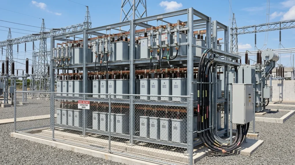
A capacitor bank is a group of two or more capacitors connected together to store and supply electrical energy in the form of reactive power. Its primary purpose is to improve the power factor of an electrical system, reduce power losses, and improve voltage stability.
Unlike a single capacitor, a capacitor bank provides a larger amount of reactive power, making it suitable for commercial and industrial electrical systems.
Simple Explanation
Many electrical machines such as motors, transformers, and welding equipment require reactive power to operate. This reactive power increases the current flowing through the electrical system, leading to higher losses and lower efficiency.
A capacitor bank supplies this reactive power locally, reducing the amount drawn from the power source.
Practical Example
Suppose an industrial factory has several induction motors. Without a capacitor bank, the motors draw more current from the electrical supply. After installing a properly sized capacitor bank, the current decreases, voltage improves, and electricity bills are reduced due to improved power factor.
Capacitor Bank Working Principle
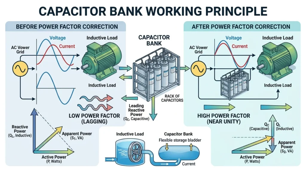
The capacitor bank working principle is based on supplying reactive power to an electrical system to improve the power factor and reduce unnecessary current flow. A capacitor bank consists of multiple capacitors connected together to store and release electrical energy in the form of an electric field. When connected to an AC power system, the capacitors generate leading reactive power that offsets the lagging reactive power produced by inductive loads such as motors, transformers, and compressors. This reduces the total current drawn from the power source, minimizes voltage drop, decreases power losses, and improves the overall efficiency of the electrical system. Capacitor banks may operate automatically or manually, switching capacitor units on or off according to the system’s reactive power demand to maintain the desired power factor and ensure stable, efficient power distribution.
The capacitor bank working principle is based on supplying reactive power to inductive loads. It generates leading reactive current, which cancels part of the lagging reactive current produced by inductive equipment.
As a result, the overall power factor improves, reducing the current drawn from the power source.
Step-by-Step Working Principle
Inductive Load Consumes Reactive Power
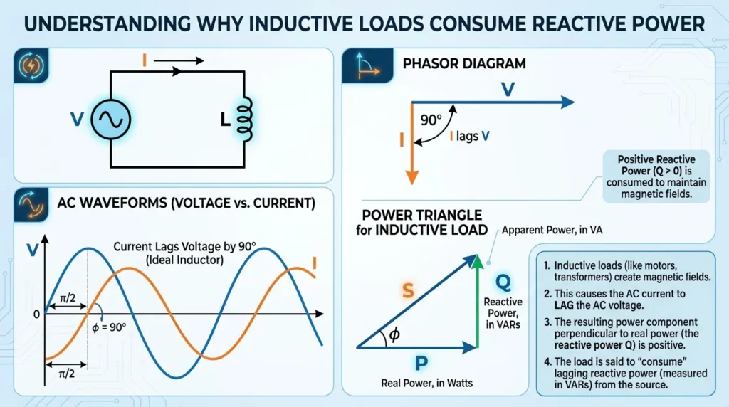
Inductive loads consume reactive power because they require a magnetic field to operate. Equipment such as electric motors, transformers, pumps, compressors, and induction furnaces draw reactive power from the AC supply to create and maintain this magnetic field. Although reactive power does not perform useful work, it is essential for the proper operation of these devices. As inductive loads consume reactive power, they cause the current to lag behind the voltage, resulting in a lower power factor. This increases the total current flowing through the electrical system, leading to higher power losses, greater voltage drop, and reduced overall efficiency. To minimize these effects, capacitor banks are commonly installed to supply reactive power locally, improve the power factor, and reduce the load on the power system.
Electrical equipment such as motors and transformers create magnetic fields during operation.
These devices consume reactive power, causing the current to lag behind the voltage.
Capacitor Bank is Connected
The capacitor bank is connected in parallel with the electrical load.
It immediately begins supplying reactive power to the system.
Capacitor Produces Leading Current
The capacitor generates current that leads the voltage.
This leading current opposes the lagging current created by inductive loads.
Reactive Power is Compensated
The leading reactive current from the capacitor bank cancels part of the lagging reactive current.
This reduces the total reactive power flowing from the utility.
Power Factor Improves
Since less reactive power is drawn from the source, the power factor increases.
Higher power factor means:
- Lower current
- Reduced power losses
- Better voltage regulation
- Improved efficiency
Easy Analogy
Imagine two people pulling a heavy cart in opposite directions. One person represents the inductive load pulling backward, while the capacitor bank pulls forward. When both forces balance, moving the cart becomes much easier. Similarly, the capacitor bank balances reactive power in an electrical system.
Types of Capacitor Bank
Different electrical systems require different capacitor bank designs.
Fixed Capacitor Bank
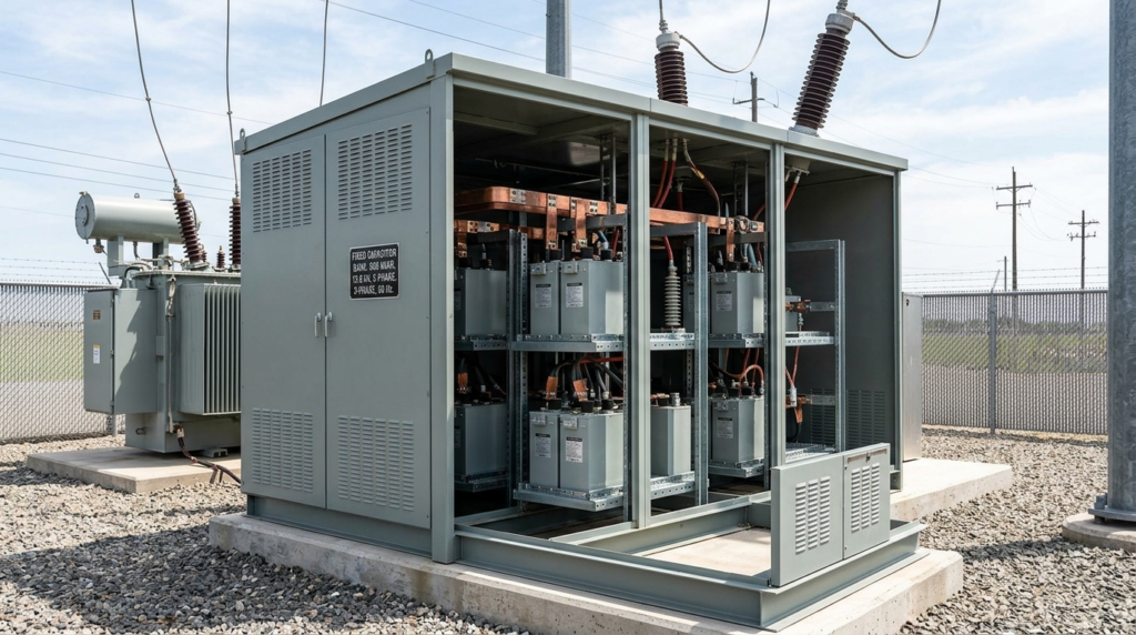
A fixed capacitor bank is a type of capacitor bank that provides a constant amount of reactive power whenever it is connected to an electrical system. It consists of one or more capacitors permanently connected to the power network and is commonly used where the electrical load remains relatively constant. Fixed capacitor banks improve the power factor, reduce reactive power demand, minimize voltage drop, and decrease power losses, resulting in better system efficiency. They are simple in design, cost-effective, and require minimal maintenance. Fixed capacitor banks are widely used in industrial plants, commercial buildings, and distribution systems with stable load conditions where continuous power factor correction is needed.
A fixed capacitor bank remains connected continuously.
Features
- Simple design
- Low cost
- Easy installation
- Suitable for constant loads
Applications
- Small industries
- Residential buildings
- Constant motor loads
Automatic Capacitor Bank

An automatic capacitor bank is a power factor correction system that automatically adjusts the amount of reactive power supplied according to the changing electrical load. It consists of multiple capacitor stages controlled by an automatic power factor controller (APFC), which continuously monitors the system’s power factor and switches capacitor units on or off as needed. This automatic operation maintains the desired power factor, reduces reactive power demand, minimizes voltage drop, and decreases energy losses. Automatic capacitor banks improve the efficiency and reliability of electrical systems while preventing overcompensation or undercompensation. They are widely used in industrial plants, commercial buildings, manufacturing facilities, and power distribution systems where electrical loads vary throughout the day.
This type automatically switches capacitor stages based on load demand.
Features
- Automatic power factor correction
- Controlled by a power factor relay
- Saves energy
- Prevents overcompensation
Applications
- Commercial buildings
- Large industries
- Variable load systems
Pole-Mounted Capacitor Bank
Installed on distribution poles.
Features
- Improves distribution voltage
- Reduces feeder losses
- Used by utility companies
Applications
- Rural power distribution
- Urban distribution networks
Substation Capacitor Bank
Installed inside electrical substations.
Features
- High voltage operation
- Large reactive power capacity
- Supports transmission systems
Applications
- Transmission networks
- Power substations
- Utility grids
Metal-Enclosed Capacitor Bank
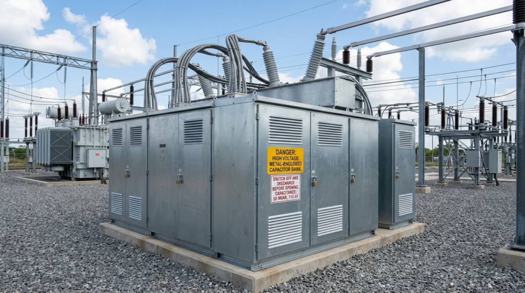
A metal-enclosed capacitor bank is a type of capacitor bank in which the capacitors and associated electrical equipment are housed inside a strong, grounded metal enclosure. The enclosure protects the internal components from dust, moisture, accidental contact, and harsh environmental conditions, while also improving operator safety. In addition to the capacitors, it may contain circuit breakers, fuses, contactors, switches, protective relays, and control devices. Metal-enclosed capacitor banks are designed to improve the power factor, reduce reactive power demand, minimize energy losses, and enhance the efficiency of electrical systems. They are widely used in industrial plants, commercial buildings, substations, and power distribution networks where safety, reliability, and ease of maintenance are important.
Capacitors are installed inside a protective enclosure.
Features
- High safety
- Weather protection
- Compact design
Applications
- Industrial plants
- Outdoor installations
Main Components
A capacitor bank consists of several important components working together.
Capacitor Units
Function:
- Store electrical energy
- Supply reactive power
- Improve power factor
Contactor
Function:
- Connects or disconnects capacitor stages
- Controlled manually or automatically
Power Factor Controller
Function:
- Monitors system power factor
- Switches capacitor stages automatically
Circuit Breaker
Function:
- Protects the capacitor bank from faults
- Disconnects during overload or short circuit
Fuses
Function:
- Protect individual capacitor units
- Prevent damage during faults
Discharge Resistors
Function:
- Safely discharge stored energy
- Protect maintenance personnel
Busbars
Function:
- Connect all capacitor units electrically
- Carry current safely
Protective Relay
Function:
- Detects abnormal conditions
- Trips the circuit breaker when required
Capacitor Bank Advantages
Understanding the capacitor bank advantages and disadvantages helps in deciding whether it is suitable for a particular electrical system.
Advantages
- Improves power factor
- Reduces electricity bills
- Lowers transmission losses
- Reduces voltage drop
- Increases system efficiency
- Improves voltage regulation
- Increases equipment life
- Releases transformer capacity
- Reduces cable heating
- Supports stable electrical operation
- Improves overall system reliability
- Requires relatively low maintenance
Capacitor Bank Disadvantages / Limitations
Although capacitor banks offer many benefits, they also have some limitations.
- Initial installation cost can be high.
- Incorrect sizing causes overcompensation.
- Harmonics may damage capacitors.
- Requires periodic inspection.
- Capacitors gradually lose capacitance over time.
- Switching transients may occur.
- Overvoltage conditions can reduce service life.
- Protective devices increase system complexity.
Capacitor Bank Applications
The wide range of capacitor bank applications makes them essential in modern electrical systems.
Home Applications
- Large residential buildings
- Solar energy systems
- Backup power systems
Commercial Applications
- Shopping malls
- Hospitals
- Office buildings
- Hotels
Industrial Applications
- Motor control centers
- Manufacturing plants
- Steel industries
- Cement factories
- Textile mills
- Food processing plants
Utility Applications
- Distribution networks
- Electrical substations
- Transmission systems
- Voltage support
Renewable Energy
- Wind farms
- Solar power plants
- Battery energy storage systems
Modern Technology
- Data centers
- Electric vehicle charging stations
- Smart grids
- Industrial automation
- Microgrids
Comparison: Capacitor Bank vs Synchronous Condenser
The difference between capacitor bank and synchronous condenser is important when selecting a reactive power compensation method.
| Feature | Capacitor Bank | Synchronous Condenser |
| Working Principle | Static reactive power compensation | Rotating machine supplying reactive power |
| Moving Parts | No | Yes |
| Maintenance | Low | High |
| Initial Cost | Lower | Higher |
| Efficiency | High | Moderate |
| Response Time | Fast | Moderate |
| Installation | Simple | Complex |
| Best Use | Most industrial power factor correction | Large utility systems requiring dynamic voltage support |
Selection Guide
Choosing the correct capacitor bank requires careful evaluation of the electrical system.
Determine Load Requirement
Calculate the reactive power required before selecting a capacitor bank.
Check Power Factor
Measure the existing power factor and determine the desired target value.
Select Proper Voltage Rating
The capacitor bank voltage rating should match or exceed the system voltage.
Consider Harmonics
If harmonic-producing equipment is present, use detuned or harmonic filter capacitor banks.
Choose Automatic or Fixed
Fixed capacitor bank:
- Constant load
Automatic capacitor bank:
- Variable load
Verify Installation Environment
Consider:
- Indoor or outdoor use
- Temperature
- Dust
- Moisture
- Ventilation
Safety Features
Select systems with:
- Circuit breakers
- Protective relays
- Discharge resistors
- Proper grounding
Common Problems & Solutions
Why is the capacitor bank overheating?
causes:
- Poor ventilation
- Overloading
- Harmonic currents
Solution:
Improve cooling and check system loading.
Why is the power factor still low?
causes:
- Incorrect capacitor size
- Failed capacitor units
- Controller malfunction
Solution:
Inspect capacitor stages and verify sizing.
Why is the circuit breaker tripping?
causes:
- Short circuit
- Capacitor failure
- Excessive switching current
Solution:
Inspect the capacitor bank and replace damaged components.
Why are capacitor units bulging?
causes:
- Internal pressure
- Overvoltage
- Aging
Solution:
Replace swollen capacitors immediately.
Why is there excessive switching noise?
causes:
- Faulty contactor
- Loose connections
- High switching frequency
Solution:
Inspect contactors and tighten all electrical connections.
Future Trends
Capacitor bank technology continues to evolve with the growing demand for efficient and intelligent power systems.
Future developments include:
- Smart capacitor banks with remote monitoring
- IoT-enabled power factor correction systems
- AI-based energy optimization
- Self-healing capacitor technology
- Harmonic filtering capacitor banks
- Predictive maintenance using sensors
- Integration with renewable energy systems
- Compact high-capacity capacitor designs
- Cloud-based energy management
- Improved safety and automatic fault detection
These innovations will help industries achieve better energy efficiency, improved reliability, and reduced operating costs.
Conclusion
A Capacitor Bank is an essential component in modern electrical systems because it improves power factor, reduces energy losses, and enhances voltage stability. Understanding the capacitor bank working principle helps students and professionals appreciate how reactive power compensation improves the efficiency of electrical networks. Different types of capacitor banks are available for residential, commercial, industrial, and utility applications, allowing engineers to choose solutions that match specific system requirements. Although capacitor banks require proper sizing, protection, and maintenance, their benefits usually outweigh their limitations by lowering electricity costs and improving equipment performance. As smart grids, renewable energy systems, and intelligent monitoring technologies continue to grow, capacitor banks will remain a key solution for efficient and reliable power distribution. Building a strong understanding of this topic is an important step toward mastering electrical power systems.