
Every digital device — your phone, your laptop, a washing machine controller — decides with logic gates. A logic gate takes binary inputs and produces one binary output by a fixed rule. Combine enough gates and you can build a calculator, or a processor.
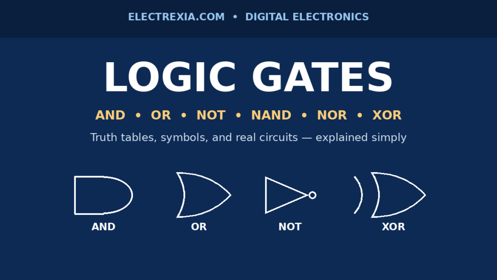
This guide covers the seven logic gates — AND, OR, NOT, NAND, NOR, XOR, and XNOR — each with its symbol, Boolean expression, and truth table, plus how gates are built and used.
What Is a Logic Gate?
A logic gate works with only two values: 0 and 1, also called LOW and HIGH. In circuits these are voltages: in TTL, LOW is 0 to about 0.8 V and HIGH is 2 V to 5 V. CMOS logic, running on 3.3 V or 5 V, uses similar thresholds.
That two-valued system comes from Boolean algebra, the mathematics of true and false from George Boole (1854). In 1938, Claude Shannon showed it could describe switching circuits.
A gate has one or more inputs and one output. Its truth table fully describes its behavior: it lists every input combination and output — a two-input gate has four combinations (2² = 4 rows). Inside, a gate is built from transistors made from a semiconductor — almost always silicon — which is why gates can be microscopic and packed by the billions into a chip.
The Basic Gates: AND, OR, and NOT
AND, OR, and NOT are the basic gates — every other gate is built from them.
AND Gate
An AND gate outputs 1 only when all inputs are 1; if any input is 0, the output is 0. Y = A · B, and its symbol is a flat-backed D shape. Two switches in series with a lamp light it only when both are closed. AND gates work as enable controls — a signal passes only when the enable input is HIGH.
| A | B | Y = A · B |
|---|---|---|
| 0 | 0 | 0 |
| 0 | 1 | 0 |
| 1 | 0 | 0 |
| 1 | 1 | 1 |
OR Gate
An OR gate outputs 1 when at least one input is 1, and 0 only when every input is 0. Y = A + B, and its symbol is curved at the input and pointed at the output. Two switches in parallel light a lamp when either is closed. OR gates suit alarm systems — if any sensor trips, the output goes HIGH.
| A | B | Y = A + B |
|---|---|---|
| 0 | 0 | 0 |
| 0 | 1 | 1 |
| 1 | 0 | 1 |
| 1 | 1 | 1 |
NOT Gate
A NOT gate, also called an inverter, has one input and one output, and inverts its input: 1 in gives 0 out, and 0 in gives 1 out. Y = Ā. The symbol is a triangle with a small circle, called a bubble, at its tip — the bubble means inversion, as on NAND, NOR, and XNOR gates. NOT gates give a circuit the opposite of a signal.
| A | Y = Ā |
|---|---|
| 0 | 1 |
| 1 | 0 |
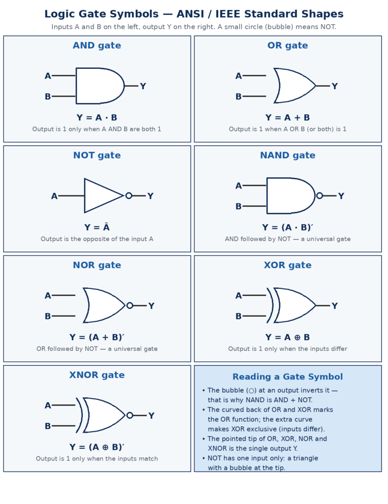
The standard ANSI/IEEE symbols for all seven gates. A bubble at the output means the output is inverted.
Universal Gates: NAND and NOR
NAND and NOR are universal gates: either one, used alone, can build every other gate and therefore any digital circuit. That is why the 7400, the most famous logic chip ever made, holds four NAND gates.
NAND Gate
A NAND gate is an AND gate followed by a NOT gate: it outputs 0 only when all inputs are 1. Y = (A · B)′, and its symbol is the AND shape with a bubble at the output. It is universal: tie both inputs together and it becomes a NOT gate; follow it with a NOT gate and you get an AND gate; and De Morgan’s law, (A · B)′ = Ā + B̄, builds an OR gate from three NANDs.
| A | B | Y = (A · B)′ |
|---|---|---|
| 0 | 0 | 1 |
| 0 | 1 | 1 |
| 1 | 0 | 1 |
| 1 | 1 | 0 |
NOR Gate
A NOR gate is an OR gate followed by a NOT gate: it outputs 1 only when all inputs are 0. Y = (A + B)′, and its symbol is the OR shape with a bubble at the output. NOR is universal for the same reason: tie its inputs together for a NOT gate, add inverters for an OR gate, and De Morgan’s law, (A + B)′ = Ā · B̄, builds an AND gate from three NOR gates. Two cross-connected NOR gates form the SR latch, which holds one bit.
| A | B | Y = (A + B)′ |
|---|---|---|
| 0 | 0 | 1 |
| 0 | 1 | 0 |
| 1 | 0 | 0 |
| 1 | 1 | 0 |
XOR and XNOR Gates
The last two gates compare their inputs — the most useful gates in arithmetic.
XOR Gate
An XOR gate, or exclusive-OR gate, outputs 1 only when its inputs are different: one 1 and one 0. Same inputs give 0. Y = A ⊕ B, and its symbol is the OR shape with an extra curved line at the input side. XOR is the gate that adds: in binary, 0 + 0 = 0, 0 + 1 = 1, 1 + 0 = 1, and 1 + 1 = 0 with a carry of 1 — the XOR truth table. So the half-adder uses an XOR gate for its sum output.
| A | B | Y = A ⊕ B |
|---|---|---|
| 0 | 0 | 0 |
| 0 | 1 | 1 |
| 1 | 0 | 1 |
| 1 | 1 | 0 |
XNOR Gate
An XNOR gate is an XOR gate followed by a NOT gate: it outputs 1 only when its inputs are the same. Y = (A ⊕ B)′, and its symbol is the XOR shape with a bubble at the output. It outputs 1 exactly when its inputs match, so it is an equality detector: one XNOR gate per bit, AND the results together, and you have a comparator that checks whether two numbers are equal.
| A | B | Y = (A ⊕ B)′ |
|---|---|---|
| 0 | 0 | 1 |
| 0 | 1 | 0 |
| 1 | 0 | 0 |
| 1 | 1 | 1 |
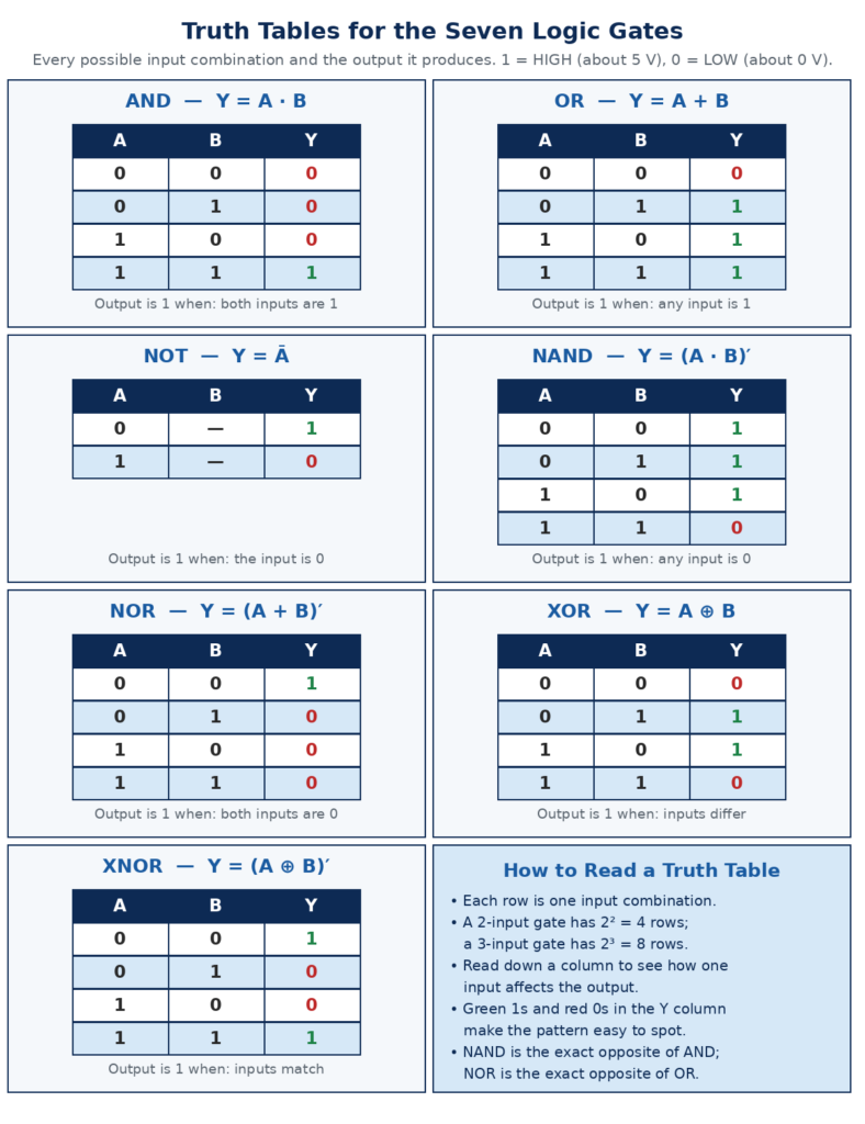
Every input combination and the output it produces. Green 1s and red 0s make each pattern easy to spot.
Logic Gates Comparison Table
Here is the whole family in one place. NAND is the opposite of AND, NOR the opposite of OR, and XOR and XNOR are opposites — four ideas: AND, OR, NOT, and “inputs differ.”
| Gate | Symbol | Boolean Expression | Output Is 1 When | Universal? |
|---|---|---|---|---|
| AND | D shape | Y = A · B | All inputs are 1 | No |
| OR | Curved input, pointed tip | Y = A + B | Any input is 1 | No |
| NOT | Triangle with bubble | Y = Ā | The input is 0 | No |
| NAND | AND shape with bubble | Y = (A · B)′ | Any input is 0 | Yes |
| NOR | OR shape with bubble | Y = (A + B)′ | All inputs are 0 | Yes |
| XOR | OR shape with extra curve | Y = A ⊕ B | Inputs differ | No |
| XNOR | XOR shape with bubble | Y = (A ⊕ B)′ | Inputs match | No |
How Logic Gates Are Built: Transistors, TTL, and CMOS
For learning, gates come packaged as 7400-series integrated circuits, introduced by Texas Instruments in 1964. Each chip holds several gates of one type:
| IC | Function | Family |
|---|---|---|
| 7400 | 4× 2-input NAND | TTL |
| 7402 | 4× 2-input NOR | TTL |
| 7404 | 6× inverter (NOT) | TTL |
| 7408 | 4× 2-input AND | TTL |
| 7432 | 4× 2-input OR | TTL |
| 7486 | 4× 2-input XOR | TTL |
| 74266 | 4× 2-input XNOR | TTL |
| 4070 | 4× 2-input XOR | CMOS |
The letters between “74” and the number name the sub-family. The original 7400 series is TTL, bipolar transistors on a fixed 5 V supply. The 74LS family kept 5 V but cut power use and sped up switching. The 74HC family uses MOSFETs, which draw almost no power when idle, and works from 2 V to 6 V. The older 4000 series is also CMOS and accepts 3 V to 18 V, handy for battery projects. Modern designs mostly use CMOS.
Three specifications decide whether a gate fits a job. Supply voltage sets the HIGH and LOW levels; mixing a 5 V TTL output with a 3.3 V CMOS input without level shifting can damage the input or produce wrong logic. Propagation delay, the time a gate takes to react, is about 10 nanoseconds for TTL and a few nanoseconds for fast CMOS. Fan-out, the number of inputs one output can drive, is about 10 for TTL and much higher for CMOS. Unused inputs must be tied to a defined level, never left floating: a floating CMOS input picks up noise and switches randomly.
Real Applications of Logic Gates
Logic gates stop being abstract when you see what they build, from processor arithmetic to a factory alarm.
Binary adders. The half-adder adds two bits with one XOR gate for the sum and one AND gate for the carry: Sum = A ⊕ B and Carry = A · B. A full-adder adds a third bit, the carry-in, with two half-adders and one OR gate: Sum = A ⊕ B ⊕ Cin and Carry-out = (A · B) + (Cin · (A ⊕ B)). Chain them together and you can add 4-bit, 8-bit, or 32-bit numbers.
Multiplexers. A multiplexer uses AND, OR, and NOT gates to route one of several inputs to a single output, selected by control lines. The reverse circuit, a demultiplexer, does the opposite.
Control and safety systems. An AND gate can require two pushbuttons pressed together before a press starts, protecting the operator’s hands. An OR gate can combine several fault sensors so that any one of them shuts a machine down. A NAND-based latch remembers an alarm state until deliberately reset. Factory controllers run thousands of these decisions in ladder logic.
Memory and storage. Two cross-coupled NAND or NOR gates form an SR latch that stores one bit. Add gating and a clock, and it becomes a D flip-flop; connect flip-flops together and you have registers, counters, and shift registers.
Everyday electronics. A washing machine controller uses gates to sequence wash, rinse, and spin. A digital clock counts pulses with flip-flops built from gates. A burglar alarm uses OR gates to combine sensors and AND gates to arm the system. Even a simple diode circuit often hands its signal to a gate.
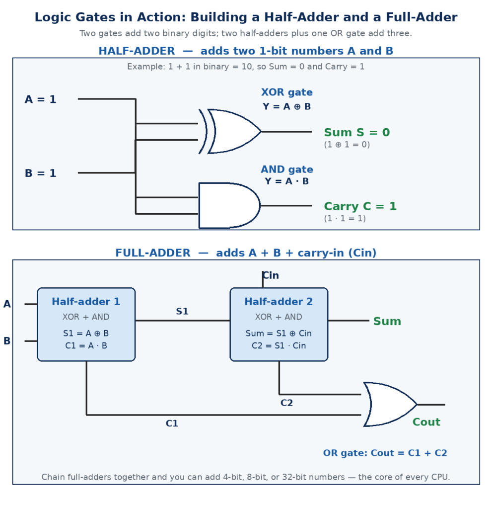
A half-adder adds two binary digits with one XOR and one AND gate; a full-adder adds three with two half-adders and an OR gate.
Frequently Asked Questions
What is a logic gate in simple words?
A logic gate is a small circuit that takes binary inputs (0 or 1) and produces one binary output. An AND gate outputs 1 only when all its inputs are 1; an OR gate outputs 1 when any input is 1.
Which logic gates are universal gates?
NAND and NOR are the universal gates: either one can build any other gate — AND, OR, NOT, XOR, or XNOR — and therefore any digital circuit. That is why the classic 7400 chip contains NAND gates.
What is the difference between XOR and OR gates?
An OR gate outputs 1 when at least one input is 1, including when both inputs are 1. An XOR gate outputs 1 only when exactly one input is 1. “Exclusive” means XOR is true for one or the other, but not both.
What voltage represents logic 1 and logic 0?
It depends on the logic family. In 5 V TTL, LOW is 0 to 0.8 V and HIGH is 2 V to 5 V. In 5 V CMOS, LOW is about 0 to 1.5 V and HIGH about 3.5 V to 5 V. In 3.3 V CMOS, HIGH is about 3.3 V and LOW is near 0 V. Logic levels are ranges, not exact values.
How many logic gates are in a computer processor?
A modern processor contains billions of transistors organized into tens or hundreds of millions of logic gates. Manufacturers count transistors, not gates — a typical desktop processor has 10 to 30 billion.
Conclusion
Logic gates turn yes-or-no rules into everything digital technology does. AND, OR, and NOT are the foundation; NAND and NOR are universal; XOR and XNOR compare inputs and make arithmetic possible. Their symbols, expressions, and truth tables are a compact language.
The next step is to build something. A 7400 NAND chip, a 7408 AND chip, a few LEDs, and a 5 V supply can test every truth table in this guide on a breadboard, and a half-adder from an XOR and an AND gate is a satisfying first project. For a deeper reference, see the guide at Wiltronics: Digital Logic Gates Explained.