
Two transformers can have identical voltage ratings and still destroy each other if connected in parallel. The reason is the transformer vector group — the code that describes how the primary and secondary windings are connected and how much the secondary voltage is phase-shifted relative to the primary. Before paralleling transformers, engineers must confirm the vector groups match; otherwise circulating currents flow even at no load.
What Is a Vector Group?
A vector group is a standardized notation (IEC 60076) describing:
- The winding connections — star (Y), delta (D), or zigzag (Z) for each side.
- The phase displacement between primary and secondary line voltages, expressed as a clock number.
It is written as a short code such as Dyn11, Yd11, or Yy0.
How to Read the Code
Letters
- First letter (capital): HV winding connection — Y (star), D (delta), Z (zigzag).
- Second letter (lowercase): LV winding connection — y, d, z.
- Optional ‘n’/’N’: neutral brought out, e.g., YNyn0.
Clock number
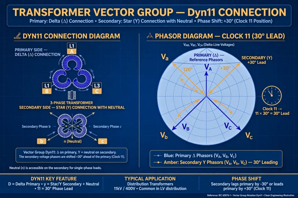
The phase displacement is given as a clock hour: each hour equals 30°. The HV line voltage is taken as the minute hand at 12, and the LV line voltage is the hour hand. So 11 means the LV lags the HV by 330° (or leads by 30°), and 0 means they are in phase.
Worked example: Dyn11
- D: HV winding in delta.
- y: LV winding in star.
- n: LV neutral available.
- 11: LV line voltage lags HV by 330° (leads by 30°).
Dyn11 is the most common distribution transformer vector group worldwide.
Reading a nameplate example
A nameplate reading “Dyn11, 1000 kVA, 11/0.433 kV” tells the full story at a glance: a 1000 kVA unit, delta on the 11 kV side, star with neutral on the 433 V side, and the secondary leading the primary by 30 degrees. Commissioning engineers check exactly this code before energizing, because a Dyn11 unit must never be paralleled with, say, a Yy0 unit even though both give the same secondary voltage. The code is the transformer’s wiring fingerprint.
Common Vector Groups
| Vector group | HV | LV | Phase shift | Typical use |
|---|---|---|---|---|
| Dyn11 | Delta | Star + neutral | 30° lead | Distribution transformers |
| Yd11 | Star | Delta | 30° lead | Generator step-up (blocks zero sequence) |
| Yy0 | Star | Star | 0° | Small transformers, needs neutral stability |
| Dd0 | Delta | Delta | 0° | Large units, unbalanced loads |
| Yz11 | Star | Zigzag | 30° lead | Distribution with heavy neutral currents |
Why Vector Groups Matter
Parallel operation
Transformers can only be paralleled if their vector groups belong to the same phase-displacement family — for example, all group 11 (Dyn11, Yd11, Yz11) or all group 0 (Yy0, Dd0). Mixing families (e.g., Dyn11 with Yy0) produces a 30° mismatch that drives large circulating currents between the units.
Conditions for paralleling
- Same voltage ratio and tap position — where fitted, the on-load tap changer must be on the same tap.
- Same vector group (or compatible group with external phase correction).
- Similar per-unit impedance (within ~10%).
- Same kVA rating ratio (ideally below 3:1).
Protection and earthing
The vector group decides which zero-sequence currents can pass through the transformer. A delta winding blocks zero-sequence current, which is why generator step-up transformers are often Yd — the delta traps triplen harmonics and earth-fault currents on the LV side.
Phase Displacement Families
- Group 0 (0°): Yy0, Dd0, Dz0 — no phase shift.
- Group 6 (180°): Yy6, Dd6 — reversed polarity.
- Group 11 (330°/30° lead): Dyn11, Yd11, Yz11 — the distribution family.
- Group 1 (30° lag): Dyn1, Yd1 — the mirror of group 11.
Transformers from different families can only be paralleled with special phase-shifting connections, which is rarely done in practice.
Testing the Vector Group
During commissioning, the vector group is verified by a phase-relation / polarity test: a low AC voltage is applied to the HV side and the induced LV voltages are measured between corresponding terminals. The measured pattern confirms the clock number on the nameplate. It is a standard part of testing a transformer before energization.
Advantages of Standard Groups
- Interchangeability: any Dyn11 transformer can replace another Dyn11 unit.
- Safe paralleling: matching groups guarantee no circulating currents from phase mismatch.
- Predictable protection: relay engineers know the phase relationships for differential schemes.
FAQs
What is a transformer vector group?
It is the IEC code (e.g., Dyn11) describing the winding connections (star, delta, zigzag) and the phase displacement between primary and secondary voltages. For the basics of the machine itself, see what a transformer is and the types of transformers.
What does Dyn11 mean?
Delta-connected HV, star-connected LV with neutral, and the LV line voltage leads the HV by 30° (clock position 11).
Why can’t two transformers with different vector groups be paralleled?
Different groups mean different phase shifts between the secondaries, which drives circulating currents between the transformers even with no load connected.
What is clock notation in transformers?
A way to express phase displacement: the HV voltage is the minute hand at 12, the LV voltage is the hour hand, and each hour represents 30° of shift.
Which vector group is used for distribution transformers?
Dyn11 is the standard for distribution transformers in most countries because the star secondary provides a neutral and handles unbalanced loads well.
How is the vector group tested?
By applying a low voltage to the HV winding and measuring the induced voltages between HV and LV terminals; the voltage pattern identifies the clock number. This quick check is done on every new transformer before first energization. See the Wikipedia article on vector groups.
Conclusion
The vector group is a small code with big consequences. It tells you how a transformer is wound, how far its secondary is phase-shifted, and — critically — which other transformers it can safely run alongside. Dyn11 rules distribution, Yd11 guards generators, and matching groups keep parallel operation free of circulating currents. Always verify the nameplate group before paralleling, and confirm it with a phase-relation test at commissioning.