

If you have ever opened a control panel and wondered how a factory machine knows when to start, stop, or wait five seconds, the answer is very often ladder logic. It is the oldest and still the most widely used way to program a programmable logic controller (PLC), and the first language most electricians learn. This guide explains rungs, contacts, coils, the motor start-stop circuit, timers, and counters.
What Is Ladder Logic?
Ladder logic is a graphical PLC programming language. A program is drawn as a ladder: two vertical power rails, with horizontal rungs between them. Each rung is one small piece of logic. Contacts on the left test conditions, such as a pressed pushbutton; a coil on the right is the result, such as a motor starter.
The formal name under IEC 61131-3 is Ladder Diagram (LD), but everyone calls it ladder logic. A PLC is a rugged industrial computer that reads inputs, runs a program, and switches outputs on and off. A SCADA system may supervise the plant from above, but the PLC does the fast, local work. Ladder logic suits true-or-false decisions such as interlocks and alarms; heavy mathematics belongs in a text language.
A Short History: From Relay Panels to PLCs
Before PLCs, control was built from banks of relays wired in large cabinets, and changing a sequence meant rewiring by hand — a job that could idle a line for days. In 1968, General Motors asked for a solid-state replacement that could be reprogrammed without rewiring. Bedford Associates, led by Dick Morley, answered with the Modicon 084.
The key decision was the programming method: a diagram that looked like the relay schematics electricians already read, so adoption was fast. In 1993, IEC 61131-3 standardized PLC programming languages, including Ladder Diagram, Function Block Diagram, Sequential Function Chart, and Structured Text. Many plants still run ladder programs written decades ago.
Anatomy of a Rung
Every ladder program is built from rungs. The diagram below shows one rung, labeled — read it left to right.
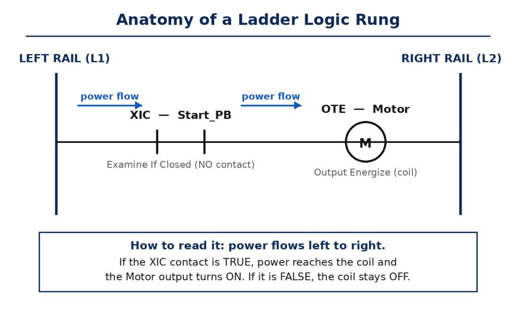
The left rail is the power rail (often L1) and the right rail is the return (often L2). Nothing in a PLC program carries real current; the rails are a convention for logic flowing left to right. Contacts sit on the left and middle of the rung, each examining one bit — a field input, an internal bit, or another output’s state. Coils sit at the far right and write a result. A rung may hold several contacts in series or parallel, but it normally ends with one coil. Rungs run top to bottom, and each deserves a short comment.
Basic Ladder Logic Symbols
You need only a handful of symbols to read most ladder programs. The mnemonics XIC, XIO, and OTE come from Rockwell Automation, which dominates the US market.
| Symbol | Name | What it does |
|---|---|---|
| —| |— | XIC — Examine If Closed (NO contact) | True when its bit is 1. |
| —|/|— | XIO — Examine If Open (NC contact) | True when its bit is 0. |
| —( )— | OTE — Output Energize (coil) | ON while the rung is true. |
| —(L)— | OTL — Output Latch | ON until unlatched. |
| —(U)— | OTU — Output Unlatch | Clears a latched bit. |
| [TON] | TON — Timer On-Delay | Waits a preset time, then turns on. |
| [CTU] | CTU — Count Up Counter | Adds one per false-to-true change. |
Two ideas trip up beginners. First, contacts test bits, not switches: a normally closed stop button can be tested with an XIC. Second, series contacts mean AND and parallel contacts mean OR.
How a Rung Works: Power Flow and the Scan Cycle
A PLC does not evaluate all rungs at once. It works through them top to bottom in a repeating loop called the scan cycle: read the inputs, execute the program, update the outputs. A typical scan takes a few milliseconds.
The PLC evaluates each rung left to right. If a continuous path of true contacts connects the left rail to the coil, the rung is true and the coil energizes; if any required contact is false, the path breaks. Because the program runs top to bottom, place the rungs that produce a value above the rungs that use it. The scan cycle also explains why a momentary pushbutton needs special handling — “run while Start is pressed” stops the motor on release. The seal-in circuit solves that.
Motor Start-Stop Circuit with a Seal-In Contact
The motor start-stop circuit is the first program every controls engineer learns. A momentary Start button starts the motor, it keeps running after release, and Stop stops it. The trick is the seal-in contact, also called a holding contact.
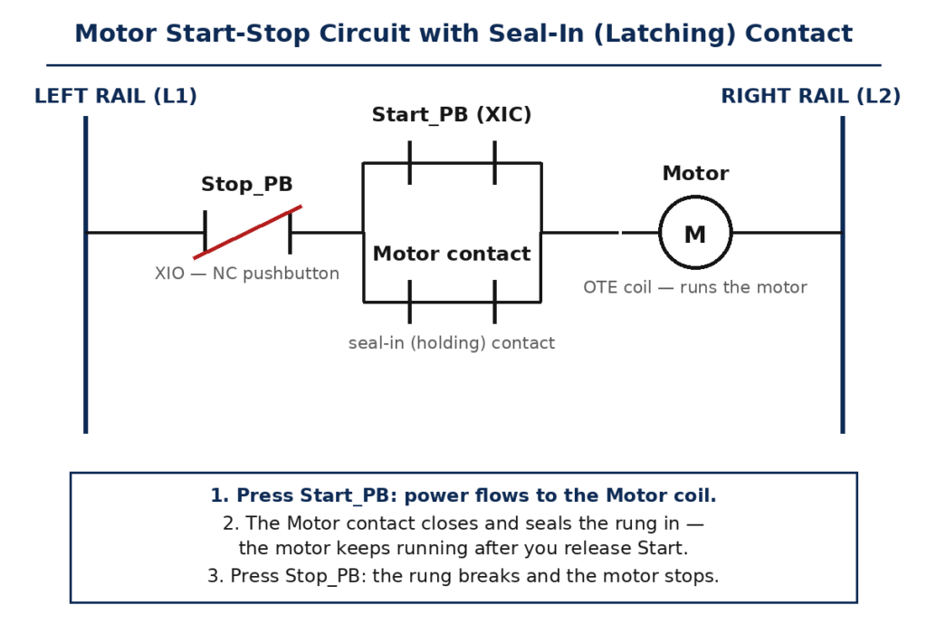
Stop is normally closed, so its XIO contact is true at rest; pressing Stop makes it false and breaks the rung — which is why Stop always wins. Start is normally open, tested with an XIC. The seal-in contact sits in parallel with Start, driven by the Motor output bit, and closes the moment the coil energizes. Press Start, and power flows to the coil; the seal-in contact closes, giving a second path. Release Start, and power keeps flowing through the seal-in contact.
Overload protection belongs in the same rung: the starter’s overload contact sits in series with Stop, so a trip drops the motor out like a Stop press, and it must be reset at the starter before restarting. The same pattern appears everywhere — a fill valve that stays open until a tank-full sensor trips is the same idea.
Timers: The On-Delay Timer (TON)
Real machines need time: a fan must keep cooling a heater after it switches off. Timer instructions handle that, and the on-delay timer, TON, is the one you will use most.
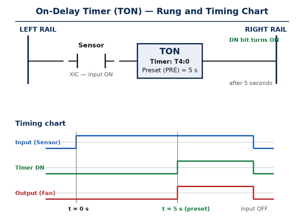
A TON has three values: the preset (PRE), the delay you want; the accumulated value (ACC), time counted so far; and the done bit (DN), which turns on only when ACC reaches PRE. For example, a sensor detects a box, and a fan must start five seconds later. The sensor enables a TON with a five-second preset; at five seconds DN turns on and a second rung starts the fan. If the sensor clears early, the timer resets.
Two mistakes to avoid: a TON resets whenever its rung goes false, so it cannot remember time across interruptions — for that use a retentive timer (RTO). And the preset must match the platform’s time base: check seconds versus milliseconds.
Counters: The Count-Up Counter (CTU)
Where timers measure time, counters measure events. A count-up counter, CTU, adds one each time its input rung changes from false to true. It counts edges, not levels: a part counts once, on arrival.
A typical use is batch counting: a sensor watches bottles on a conveyor, and each bottle makes the rung go true once. The preset (PV) holds the target — say 24 bottles per case. At 24, the done bit (DN) turns on and a second rung pushes the full case off the line. A reset (RES) clears the count to zero. Counters often pair with a one-shot, which turns a long sensor signal into one clean pulse.
Worked Example: A Start-Stop Motor Rung, Contact by Contact
Take a packaging conveyor driven by a PLC-controlled motor, with a green Start pushbutton, a red Stop pushbutton, and a healthy overload contact. The tags use plain words: Start_PB, Stop_PB, Overload_OK, and Motor.
Left to right, the rung is: Stop_PB (XIO), Overload_OK (XIC), a parallel pair of Start_PB (XIC) and the Motor seal-in contact (XIC), then the Motor coil (OTE). In text form: Motor = (Start_PB OR Motor) AND (NOT Stop_PB) AND Overload_OK.
At rest, Stop_PB and Overload_OK are true while Start_PB and the Motor contact are false, so no path exists and the coil stays off. Press Start: a path opens, the coil energizes, and the seal-in contact closes. Releasing Start changes nothing — power flows through the seal-in contact. Pressing Stop breaks the rung and the coil drops out. If Start and Stop are pressed together, Stop wins, since it sits in series with everything else: the safe behavior, and a standard commissioning test.
Ladder Logic vs. Structured Text vs. Function Block
Ladder logic is one of several IEC 61131-3 languages, each with a natural home. Structured Text (ST) suits calculations and recipes; Function Block Diagram (FBD) suits continuous processes such as PID control.
| Feature | Ladder Diagram (LD) | Structured Text (ST) | Function Block (FBD) |
|---|---|---|---|
| Form | Graphical rungs and rails | Text code | Blocks wired together |
| Best for | Boolean logic, interlocks | Math, recipes | Analog control, PID loops |
| Who reads it | Electricians, technicians | Controls engineers | Process engineers |
| Strength | Easy to read | Compact for math | Clear signal flow |
| Weakness | Weak at math | Hard for electricians | Messy for big logic |
The practical rule: ladder for machine logic maintenance must read, Structured Text for calculations, Function Block for analog loops. The languages share tags freely.
Where Ladder Logic Is Used
Ladder logic runs machines in every industry. On a packaging line it sequences fillers and labelers, counts cases, and stops the line on a jam. On conveyors it starts motors in order. In water treatment it alternates pumps. In automotive plants it controls robot interlocks and safety gates: a robot may not move unless the gate is closed, the part is present, and the previous station is clear — each condition a contact, the whole safety chain one rung. Inside the panel, that logic drives the hardware in any electrical panel design, and the starters switch power through devices built like a transistor.
FAQs
Is ladder logic the same as relay logic?
Not quite. Relay logic is physical: real relays, wires, and current. Ladder logic is software that imitates relay diagrams inside a PLC — but it can also do things no relay panel can, such as millisecond timers.
Is ladder logic still used in 2026?
Yes. It remains the most common PLC language in North America and the first taught in most automation programs. Newer languages handle calculations, but for machine logic and start-stop control, ladder is still the default.
What is the difference between XIC and XIO?
XIC is true when the bit it examines is 1; XIO is true when the bit is 0. They are the software versions of normally open and normally closed contacts, and they test a memory bit — so the same device can be tested with either.
How do I learn ladder logic as a beginner?
Start with XIC, XIO, and OTE. Build the motor start-stop circuit in a free simulator or training PLC, watch the seal-in contact work, then add one timer and one counter. Then ask a senior technician to walk you through a program on a machine you know.
Can ladder logic control analog signals?
Yes, with analog input and output modules. A temperature sensor feeds a 4-20 mA signal into the PLC, the program compares it with a setpoint, and the result drives a heater or valve. For smooth control, most programmers use a Function Block PID loop and let ladder handle start and stop.
Conclusion
Ladder logic earns its place because it is easy to read and hard to misunderstand. Two rails, a row of rungs, contacts that test conditions, and coils that drive outputs are all it takes to control a motor or sequence a line. The seal-in circuit turns a momentary press into a running machine, timers add needed delays, and counters track every part.
If you are starting out, build the start-stop circuit here until you can explain every contact. Then add a five-second timer, then a counter that stops the line after twenty-four parts.
For a deeper tutorial with worked programs and tests you can run in a browser, see the comprehensive ladder logic tutorial at PLCProgramming.io: Ladder Logic Programming: Language, Programs & Examples.