

Almost every analog circuit has one small component at its heart: the operational amplifier, or op-amp. It boosts weak sensor signals, shapes guitar-pedal sound, and compares voltages in a battery charger. One tiny 8-pin chip can amplify, add, subtract, compare, filter, and buffer signals. This guide explains what an op-amp is, how it works, the two amplifier circuits you will use most often, and the key limits of real devices.
What Is an Op-Amp?
An operational amplifier is a high-gain differential voltage amplifier on a single chip: it amplifies the difference between its two input voltages. It has an inverting input, marked (−), a non-inverting input, marked (+), and a single output. When the (+) input is higher than the (−) input, the output swings positive; otherwise it swings negative.
The name comes from its job in 1940s–1950s analog computers; the Fairchild μA741 (1968) put a complete op-amp on one chip. Inside are three stages: a differential input stage of matched transistors, a high-gain stage, and an output stage. The differential input is its key property: it responds to a difference between its inputs and ignores voltages common to both.
The Op-Amp Symbol and Pinout
On a schematic, an op-amp is a triangle pointing right. The inverting (−) input enters upper left, the non-inverting (+) input lower left, and the output leaves from the tip on the right. Power connections (V+ and V−) are often left off simplified diagrams.
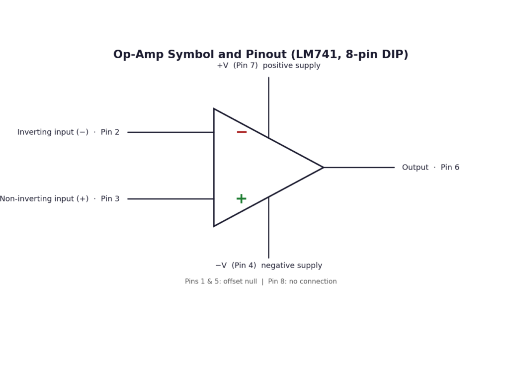
The 8-pin DIP used by the classic LM741 is the most common package, and its pinout is worth memorizing: pin 2 is the inverting input, pin 3 the non-inverting input, pin 6 the output, pin 7 the positive supply (typically +12 V or +15 V), and pin 4 the negative supply (typically −12 V or −15 V). Pins 1 and 5 are offset null, pin 8 is not connected, and many modern op-amps, such as the dual LM358, run from a single supply (for example, +5 V).
Ideal Op-Amp Characteristics
Textbook analysis uses an “ideal” op-amp: a perfect device that does not exist but is close enough for most design. The table compares each ideal value with a real 741.
| Characteristic | Ideal | 741 (typical) |
|---|---|---|
| Open-loop gain | Infinite | 200,000 |
| Input impedance | Infinite | 2 MΩ |
| Output impedance | Zero | 75 Ω |
| Bandwidth | Infinite | 1 MHz |
| Offset voltage | Zero | 1–5 mV |
| CMRR | Infinite | 90 dB |
| Slew rate | Infinite | 0.5 V/µs |
Two consequences — the golden rules — apply whenever the op-amp is wired with negative feedback.
- No current flows into either input terminal. With infinite input impedance, the inputs draw no current, so current through an input resistor continues through the feedback resistor.
- The voltage difference between the two inputs is zero. With infinite gain, the output settles where the two inputs are equal (V+ = V−) — the virtual short: the inputs behave as if shorted, though no current flows between them.
How an Op-Amp Works
On its own, without feedback, an op-amp has an enormous open-loop gain — typically 100,000 or more. A 0.1 mV input difference would theoretically produce 10 V out, but the output cannot exceed the supply rails, so even a fraction of a millivolt slams it against one rail or the other. That is why an op-amp with no feedback is almost never used as a linear amplifier.
Negative feedback fixes that: feeding a fraction of the output back to the inverting input trades most of that raw gain for stability, linearity, and a gain set by two external resistors. The output follows VOUT = AOL × (V+ − V−), and feedback adjusts VOUT until V+ and V− are nearly equal.
Inverting Amplifier
In the inverting amplifier, the input drives the inverting (−) terminal through Rin, Rf feeds the output back to the same terminal, and the (+) terminal is grounded.
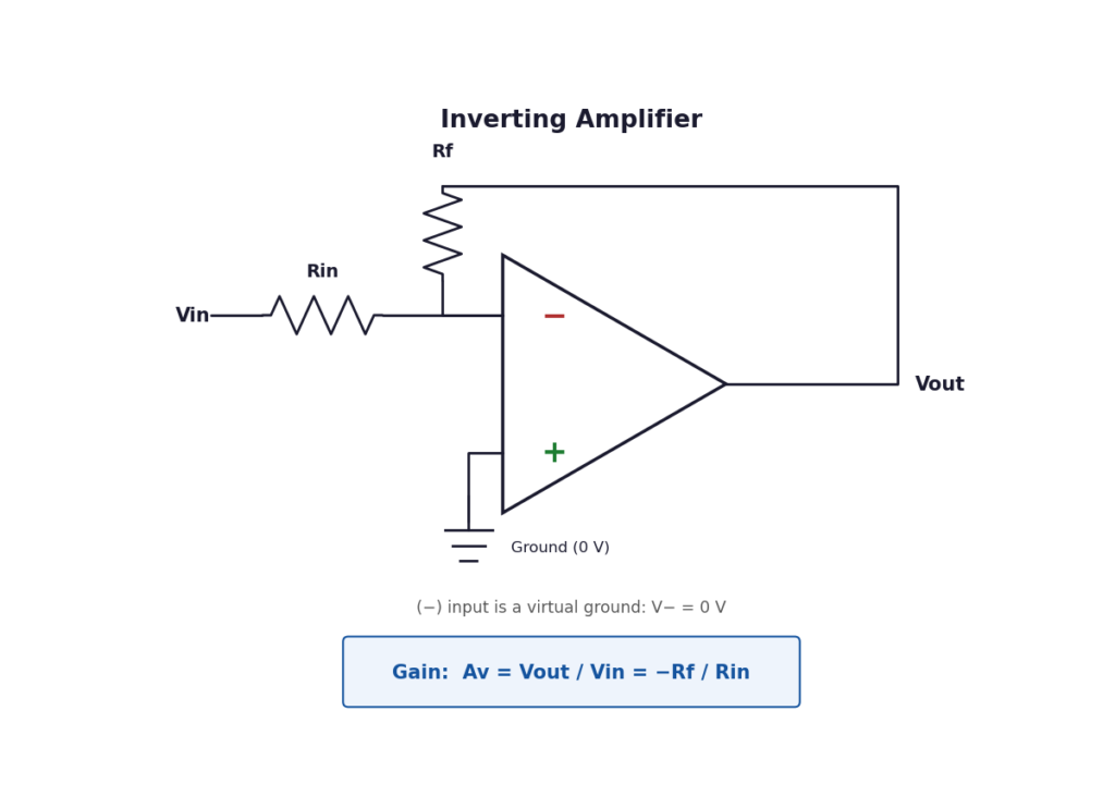
The (+) terminal is grounded, so V+ = 0 V, and the virtual short forces V− = 0 V — a virtual ground. No current enters the op-amp, so all the current through Rin flows out through Rf.
Av = Vout / Vin = −Rf / Rin
The minus sign is the whole point: the output is inverted, 180 degrees out of phase with the input. The gain is simply the resistor ratio, and it can be less than 1. Note the input impedance is approximately Rin.
Worked example. With Rin = 10 kΩ, Rf = 100 kΩ, and a 0.5 V peak sine-wave input, the gain is Av = −10, so the output is −5 V peak, inverted. With ±15 V rails, 5 V is fine — but a 2 V peak input would predict −20 V, so the output would clip at roughly ±13 V. Always check the predicted output fits inside the supply rails (use Ohm’s law).
Non-Inverting Amplifier
In the non-inverting amplifier, the input goes directly to the (+) terminal, while R1 and Rf form a divider from the output back to the (−) terminal. Input impedance is very high — typically megaohms — so it barely loads the source.
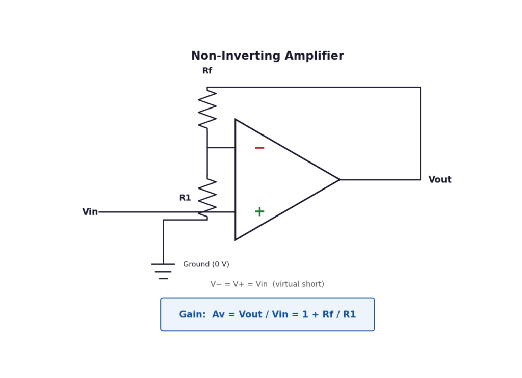
The virtual short forces V− = V+ = Vin, and the divider sets V− = Vout × R1 / (R1 + Rf).
Av = Vout / Vin = 1 + Rf / R1
The gain is always positive and at least 1 — this circuit can never attenuate. The special case Rf = 0 with R1 removed gives a gain of exactly 1: the voltage follower, covered below.
Worked example. With R1 = 1 kΩ, Rf = 9 kΩ, and a 0.3 V DC input, the gain is Av = 10, so the output is 3 V DC. On a single +5 V supply with an LM358, the output can reach only about 3.5 V — but a 0.5 V input would demand 5 V out.
Voltage Follower
The voltage follower, or unity-gain buffer, is the simplest op-amp circuit: the output is wired straight back to the inverting input, and the signal goes into the (+) input. Its gain is exactly 1, so the output copies the input voltage. That sounds useless until you consider impedance: the follower draws almost no current, yet can drive a heavy load.
A classic use is buffering a high-impedance sensor, such as a pH probe, before an analog-to-digital converter.
Differential and Summing Amplifiers
A differential amplifier (subtractor) feeds one signal to the (+) input and another to the (−) input; the output equals the difference times a resistor ratio. It sits behind instrumentation amplifiers for bridge sensors, strain gauges, and thermocouples.
A summing amplifier is an inverting amplifier with several input resistors feeding the same virtual-ground node, so the output is the (inverted) weighted sum of all the inputs. Audio mixers use exactly this circuit.
Op-Amp as a Comparator
Remove the feedback entirely and the op-amp becomes a comparator. With its enormous open-loop gain, any positive input difference drives the output to the positive saturation voltage, and any negative difference to the negative saturation voltage. Feed a sensor voltage into one input and a fixed reference into the other, and the output flips as the sensor crosses it.
Comparators serve as zero-crossing detectors, battery-charger level detectors, and thermostat switches. A bare op-amp makes a poor comparator in fast or noisy circuits, so dedicated chips such as the LM339 are used instead.
Key Parameters You Must Know
Ideal rules work on paper, but five real-world parameters decide whether a circuit works on the bench:
- Slew rate: the fastest rate the output voltage can change, in V/µs. A 741 manages about 0.5 V/µs, so a large fast sine wave comes out triangular; for faster signals use the TL081 at 13 V/µs.
- Gain-bandwidth product (GBW): gain times bandwidth is roughly constant: a 741 with a 1 MHz GBW gives about 100 kHz at a gain of 10, but only 10 kHz at 100.
- Common-mode rejection ratio (CMRR): how well the op-amp ignores voltages common to both inputs. At 90 dB, a common-mode signal is attenuated about 30,000 times.
- Input offset voltage: the small voltage needed between the inputs to force the output to zero — typically 1–5 mV in a 741. Multiplied by the gain, it appears as a DC error, so precision circuits use low-offset op-amps.
- Saturation and output swing: the output cannot reach the supply rails. A 741 on ±15 V supplies swings to about ±13 V; an LM358 on a single 5 V supply reaches roughly 0 V to 3.5 V. Ask for more and the output clips.
Popular Op-Amps Compared
All values are typical — confirm them in the datasheet.
| Specification | LM741 | LM358 | TL081 |
|---|---|---|---|
| Type | Single, bipolar | Dual, bipolar | Single, JFET input |
| Supply voltage | ±5 V to ±22 V | 3 V to 32 V | ±5 V to ±18 V |
| Gain-bandwidth | 1 MHz | 1 MHz | 3 MHz |
| Slew rate | 0.5 V/µs | 0.3 V/µs | 13 V/µs |
| CMRR (typical) | 90 dB | 85 dB | 86 dB |
| Input impedance | 2 MΩ | 2 MΩ | 1012 Ω |
| Best for | Learning, general | Single-supply, battery | Fast, high-impedance |
Pick the LM358 for a single 5 V rail, the TL081 for fast signals, and the 741 for learning — and always check the semiconductor datasheet.
Practical Applications
Op-amps turn up in places most people never notice. In audio, they form microphone preamplifiers, tone controls, and headphone drivers. In instruments, they buffer sensors, amplify thermocouple and strain-gauge signals, and build precision rectifiers for millivolt AC signals — a job an ordinary diode rectifier cannot do.
Control systems use op-amps as error amplifiers comparing a setpoint with a measured value to drive a motor or heater. Active filters built from them select or reject frequency bands in radios, hearing aids, and equalizers without bulky inductors.
FAQs
What does an op-amp do?
An op-amp amplifies the voltage difference between its two inputs; with a few resistors as negative feedback, its gain is set by resistor values.
Inverting vs non-inverting amplifier: what is the difference?
In an inverting amplifier the input goes through a resistor to the (−) terminal, the output is 180 degrees out of phase, and the gain is −Rf/Rin (it can be less than 1). In a non-inverting amplifier the input goes to the (+) terminal, the output stays in phase, and the gain is 1 + Rf/R1 — always at least 1.
Why is the 741 op-amp still used?
The 741 is cheap, widely available, and pin-compatible with many newer parts, so it remains the standard teaching op-amp. For new designs, use the LM358 for single-supply circuits and the TL081 for faster signals.
Can an op-amp run from a single power supply?
Yes, with a single-supply part such as the LM358, which works with its negative rail at ground. A standard 741 expects a dual supply (for example, ±15 V), and no op-amp output can reach either rail exactly.
What happens when an op-amp output saturates?
The output clips slightly inside the supply rails (about ±13 V for a 741 on ±15 V supplies), flattening the waveform peaks. Fix it by reducing the gain or input signal, or by raising the supply voltage.
Conclusion
An op-amp is a high-gain differential amplifier that becomes a precise block once negative feedback is applied. Two golden rules — no current into the inputs, and equal voltages at the two inputs — analyze the inverting amplifier (gain −Rf/Rin), the non-inverting amplifier (gain 1 + Rf/R1), the voltage follower, and the summing and differential circuits. Real devices add limits: finite slew rate and gain-bandwidth product, input offset voltage, finite CMRR, and an output that never quite reaches the supply rails.
Try the two worked examples on a breadboard, both on ±12 V or ±15 V supplies, and deliberately drive one into clipping. For a deeper treatment, see the op-amp tutorial at Expert Study Guides.