


A MOSFET is a voltage-controlled transistor used for switching and amplification in almost every modern electronic device. The name stands for metal-oxide-semiconductor field-effect transistor, and it describes exactly how the device is built and how it behaves: a voltage applied to an insulated metal gate creates an electric field that controls how easily current flows through a semiconductor channel. MOSFETs switch power supplies, drive motors, dim LEDs, and form the billions of logic switches inside every computer processor and memory chip.
The MOSFET was invented in 1959 at Bell Telephone Laboratories by Mohamed Atalla and Dawon Kahng. It is now the most widely manufactured device in history — trillions are produced every year. Its key advantage over the older bipolar transistor is that it is controlled by voltage, not current: once the gate is charged, holding the device on costs almost no steady power. That is why MOSFETs dominate switching circuits, from a phone charger to an electric vehicle motor drive.
How a MOSFET Works
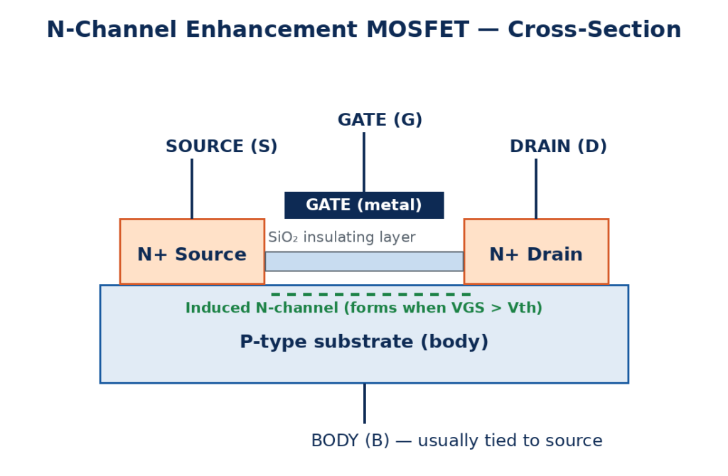
A MOSFET has three working terminals: the gate (G), the drain (D), and the source (S). The gate sits above the semiconductor body but is separated from it by a very thin layer of silicon dioxide, an electrical insulator. Because of this insulation, the gate draws essentially no steady current — it behaves like one plate of a small capacitor.
Consider the most common type, the N-channel enhancement MOSFET. It is built on a P-type substrate with two highly doped N-type regions that form the source and the drain. With no gate voltage, there is no conducting path between source and drain, so the device is off. When a positive voltage is applied to the gate, the electric field attracts electrons to the surface under the gate and forms a thin N-type channel connecting source and drain. Current can now flow. The higher the gate-source voltage (VGS), the stronger the channel and the more current flows.
The gate-source voltage at which the channel first forms is called the threshold voltage (Vth), typically 1 to 4 V for power MOSFETs and below 1 V for logic-level devices. Below Vth the device is off; above it, the device conducts. Because the channel is formed by an electric field rather than by injecting current, the MOSFET is described as a voltage-controlled device.
Types of MOSFETs
MOSFETs are sorted along two independent axes, and combining them gives four standard types:
| Type | Channel | At VGS = 0 | How to Turn On |
|---|---|---|---|
| N-channel enhancement | N-type | Normally off | Apply positive VGS above Vth |
| P-channel enhancement | P-type | Normally off | Apply negative VGS below Vth |
| N-channel depletion | N-type | Normally on | Apply negative VGS to turn off |
| P-channel depletion | P-type | Normally on | Apply positive VGS to turn off |
Enhancement-mode devices are the most common by far — about 99 percent of modern power applications use them, because “normally off” is the safe choice for a switch. N-channel MOSFETs are used for low-side switching, with the source connected to ground. P-channel MOSFETs are used for high-side switching, with the source connected to the positive supply. Depletion-mode devices are normally on and are used mainly as constant-current sources and in special analog circuits.
MOSFET Characteristics and Formulas
A MOSFET operates in three regions. In the cutoff region (VGS below Vth), the device is off and the drain current is nearly zero. In the linear (triode) region, the channel acts like a voltage-controlled resistor. In the saturation region, the drain current is set mainly by the gate voltage and becomes nearly independent of the drain-source voltage. Switching circuits drive the MOSFET hard between cutoff and the linear region; amplifiers bias it in saturation.
In saturation, the drain current follows the square-law formula:
ID = k × (VGS − Vth)²
Here k is a device constant that depends on the size and construction of the MOSFET. Always use the datasheet curves for real design, because k and Vth vary with temperature and between individual parts.
When a MOSFET is used as a switch, the most important number is the on-state resistance, RDS(on). A fully-on MOSFET behaves like a small resistor, and its conduction loss is:
P = ID² × RDS(on)
Worked example: a MOSFET with RDS(on) of 0.05 Ω switching a 12 V, 2 A motor load dissipates P = 2² × 0.05 = 0.2 W. That is low enough to run without a heatsink. Compare that with a bipolar transistor in the same job, which would drop about 0.5 to 1 V and dissipate 1 to 2 W. This is a large part of why MOSFETs dominate efficient power switching.

MOSFET vs BJT
The MOSFET and the bipolar junction transistor can both act as switches or amplifiers, but they are controlled in fundamentally different ways. A BJT is current-controlled: base current commands a larger collector current. A MOSFET is voltage-controlled: gate voltage governs the channel.
| Feature | MOSFET | BJT |
|---|---|---|
| Control quantity | Gate-source voltage | Base current |
| Input impedance | Very high (insulated gate) | Low (draws base current) |
| Steady drive power | Almost zero once gate is charged | Continuous base current while on |
| Switching speed | Very fast, no carrier storage time | Slower, storage-time delay |
| Carriers | Majority carriers only (unipolar) | Electrons and holes (bipolar) |
| Thermal behavior | Positive temperature coefficient, self-limiting | Risk of thermal runaway |
| Best for | Switching, digital logic, power conversion | Linear analog, low-noise, low-current work |
The MOSFET also differs from the IGBT, its high-power cousin. An IGBT combines a MOSFET input with a bipolar output, which gives it the MOSFET’s easy voltage drive and the BJT’s high-current capability. As a rule of thumb, MOSFETs are preferred below about 600 V and at high switching frequencies, while IGBTs take over at higher voltages and currents, such as in large motor drives and solar inverters.

Applications of MOSFETs
- Switch-mode power supplies (SMPS): MOSFETs switch at tens or hundreds of kilohertz in laptop adapters, phone chargers, and DC-DC converters, making power conversion efficient and compact.
- Motor control: MOSFETs drive DC motors, brushless motors, and stepper motors with pulse-width modulation (PWM) in robots, drones, electric vehicles, and power tools.
- Digital circuits: billions of MOSFETs form CMOS logic gates in processors, memory chips, and microcontrollers, switching with almost no static power.
- LED dimming: PWM switching through a MOSFET controls LED brightness smoothly and efficiently.
- Battery protection: MOSFETs disconnect a battery on overcharge, over-discharge, or short circuit in phones, laptops, and power tools.
- Audio amplifiers: MOSFETs are used in high-power audio output stages for their fast switching and thermal stability.
- Load switching: a MOSFET lets a microcontroller switch a load far heavier than its own pins can drive, such as a heater, solenoid, or relay.
MOSFETs rarely work alone. A diode is often placed across an inductive load to absorb voltage spikes, and MOSFETs sit at the heart of the rectifier and converter circuits used in power supplies.
Frequently Asked Questions
What does MOSFET stand for?
MOSFET stands for metal-oxide-semiconductor field-effect transistor. The name describes its structure: a metal gate, an oxide insulating layer, and a semiconductor channel controlled by an electric field.
What is the difference between a MOSFET and a transistor?
A MOSFET is a type of transistor. The common bipolar transistor (BJT) is controlled by base current, while a MOSFET is controlled by gate voltage. MOSFETs have much higher input impedance, switch faster, and need almost no steady drive power.
How do I choose a MOSFET for a project?
Check four datasheet numbers: the maximum drain-source voltage (VDS) must exceed your supply voltage with margin, the continuous drain current (ID) must exceed your load current, RDS(on) should be low enough to keep conduction losses small, and the threshold voltage (Vth) must suit your control voltage — a logic-level MOSFET turns fully on at 5 V or 3.3 V.
Why does a MOSFET need a gate resistor?
The gate acts like a capacitor. When it switches, it briefly draws a surge of current to charge or discharge. A small gate resistor (typically 10 to 100 Ω) limits this surge, protects the driving microcontroller pin, and controls switching speed to reduce electrical noise.
Can a MOSFET be damaged by static electricity?
Yes. The thin gate oxide layer can be punctured by static discharge, so MOSFETs should be handled with ESD precautions: grounded wrist straps, anti-static packaging, and avoiding touching the gate pin directly.
Conclusion
The MOSFET is the workhorse of modern electronics because it turns a voltage into controlled current with almost no wasted drive power. Its insulated gate, fast switching, and low on-state resistance make it the default choice for power supplies, motor drives, LED control, and the digital logic inside every computer. Understand its four types, the threshold voltage, and the RDS(on) loss formula, and you can select and drive a MOSFET for almost any switching job. For a fuller selection guide with practical parameter advice, see this MOSFET guide: What Is a MOSFET? Working Principle, Types, and Selection Guide.